How to Replace a Front Wheel Hub on a 1974 Dodge W-100
Due to negligence on my own part, I had to replace the front right wheel hub on my W-100 soon after I bought it. After exhausting every resource I could in an attempt to find the proper replacement procedures, I came to the realization that for my particular vehicle there was no repair procedure. My theory is that I have a late-year model of truck, where the construction was changed but the service literature was not updated to reflect this change.
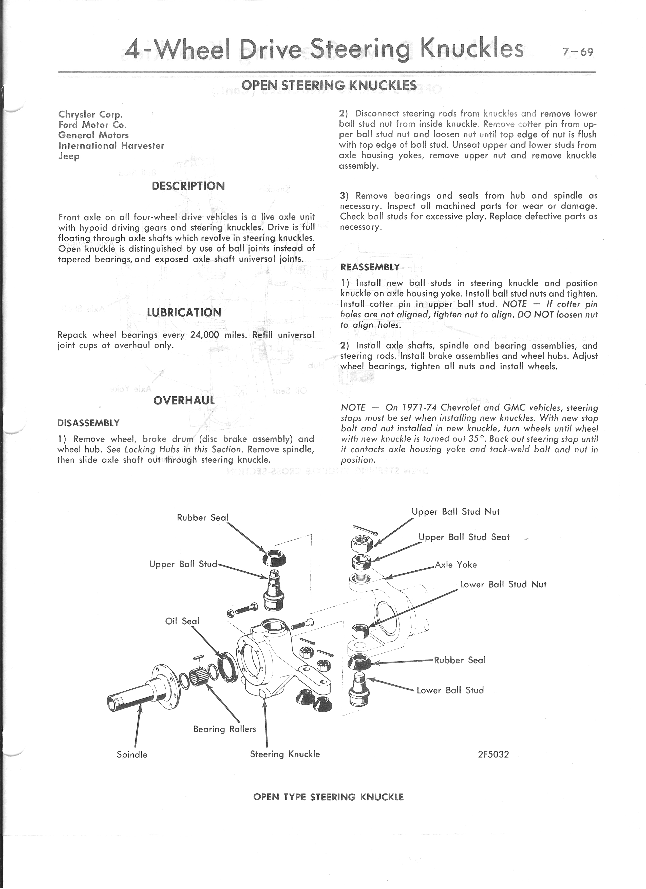
I have a truck with open steering knuckles on a Dana 44 front axle. Most people have my type of truck with closed steering knuckles on a Dana 44 front axle, particularly if it was built in 1970 through 1973. At least that's what I gather from the assorted How-Tos detailing how to convert to front disc brakes. That is a completely different modification, of which I will not go into here because I do not have that particular setup, and I have not done the conversion on my vehicle.
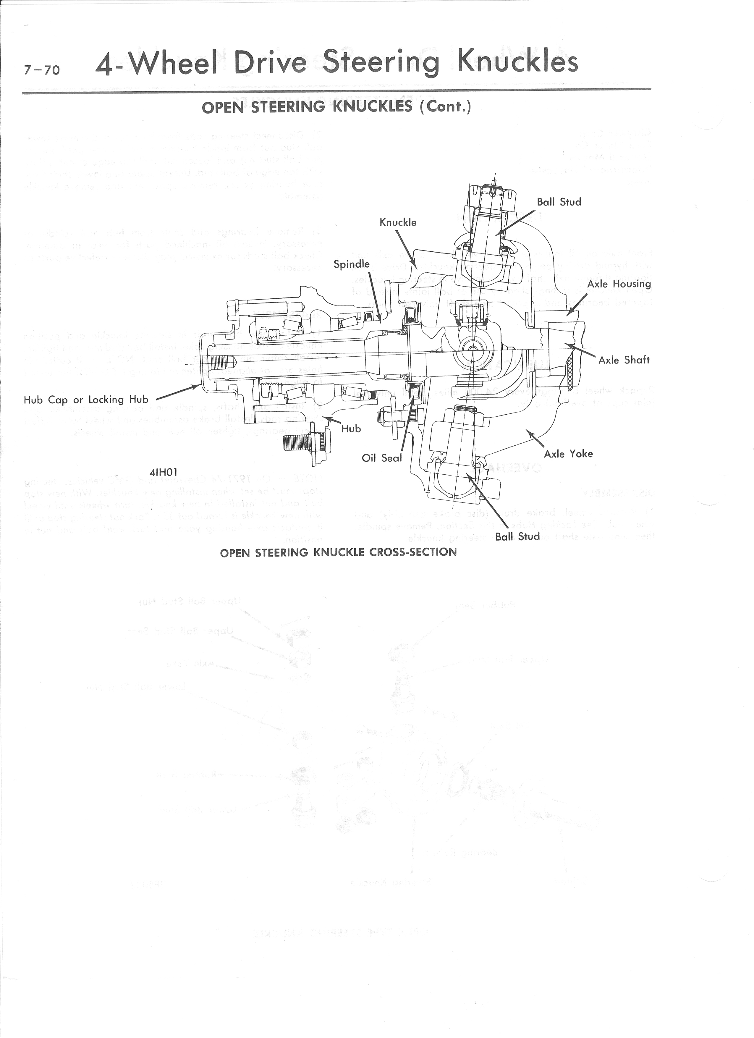
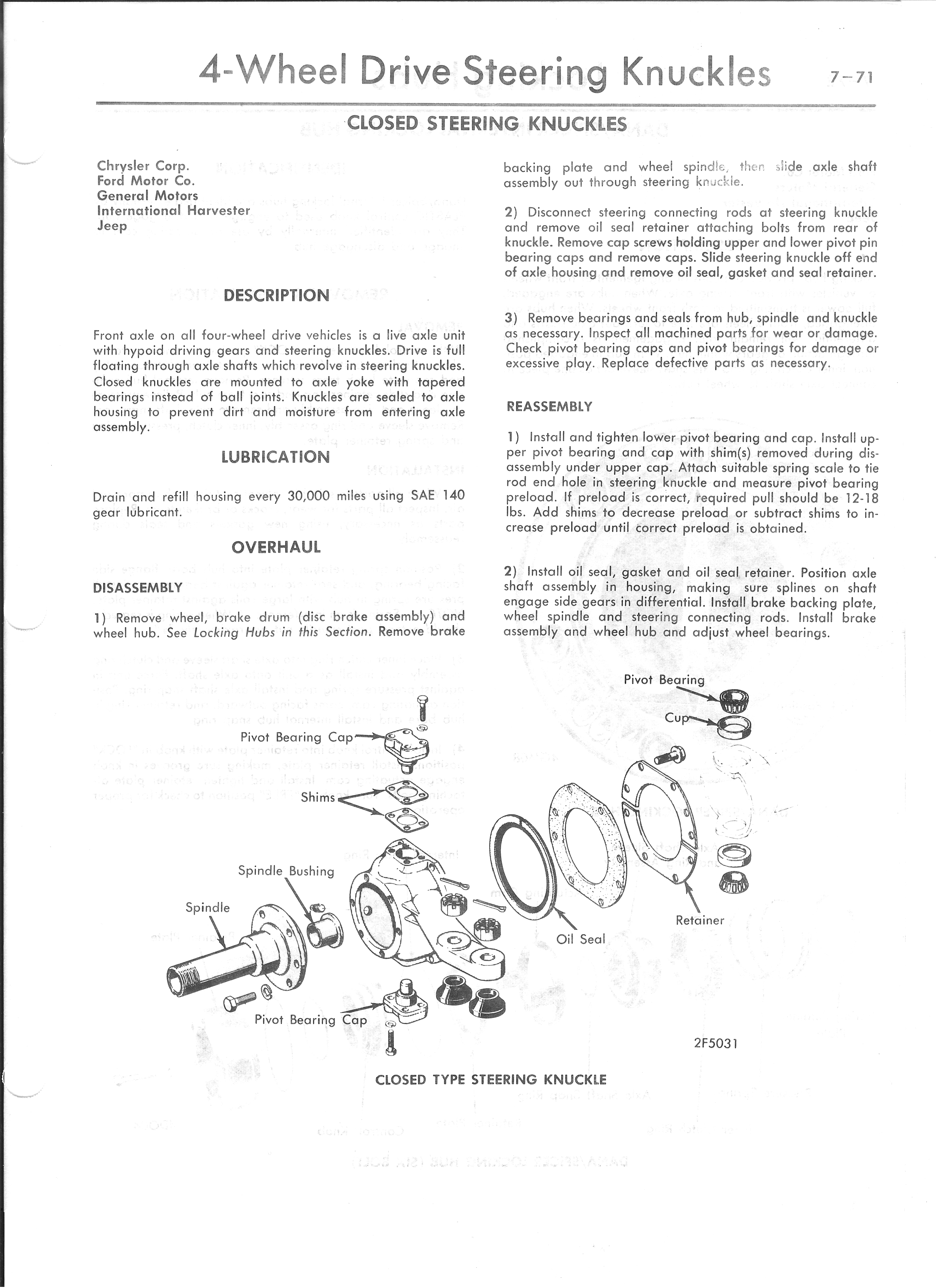
The closest information I could find on my vehicle was in a Mitchell generic truck service manual. It had an exploded diagram of an open steering knuckle design, with some basic information, as well as a cross-section diagram. I also have a page detailing a closed knuckle steering design. They are shown below.
|
|
|
|
I wrote this how-to because I know how frustrating it is to not have the information you need. I am increasingly annoyed by factory service manuals which include service procedures about every model year vehicle except your own, and do not include decent pictures to boot. Hopefully someone else with a similar problem will find this page helpful.
The photos provided below, while illustrating quite a bit of the entire procedure, are not an entirely in-depth guide. I did the entire repair on my own, and as such was unable to take photographs of all the steps. However, they will aid the entire procedure which I will outline in text. Part numbers will be provided.
I also took the opportunity to bead blast and repaint my brake backing plates, and do a complete front brake job. This may not be required for you. If so, simply disregard those steps and skip ahead.
Special Tools Required:
4WD spindle nut socket for 1970 vintage Dana 44 axles. Available from
KD Tools, Lisle, and probably a number of other manufacturers.
Approximately twenty dollars at a parts store.
Inside retaining clip pliers.
Special Tools Suggested:
Bearing race and seal driver set. If a race and seal
driver is not available, a small, long drift or pin punch and a sturdy chunk of
2x4 about six inches in length will suffice.
Bearing packer.
Parts List:
Timken inner bearing, LM01349
Timken bearing,
Timken inner bearing race, LM501310
Timken rear bearing race, LM603011
Timken inner wheel hub seal,
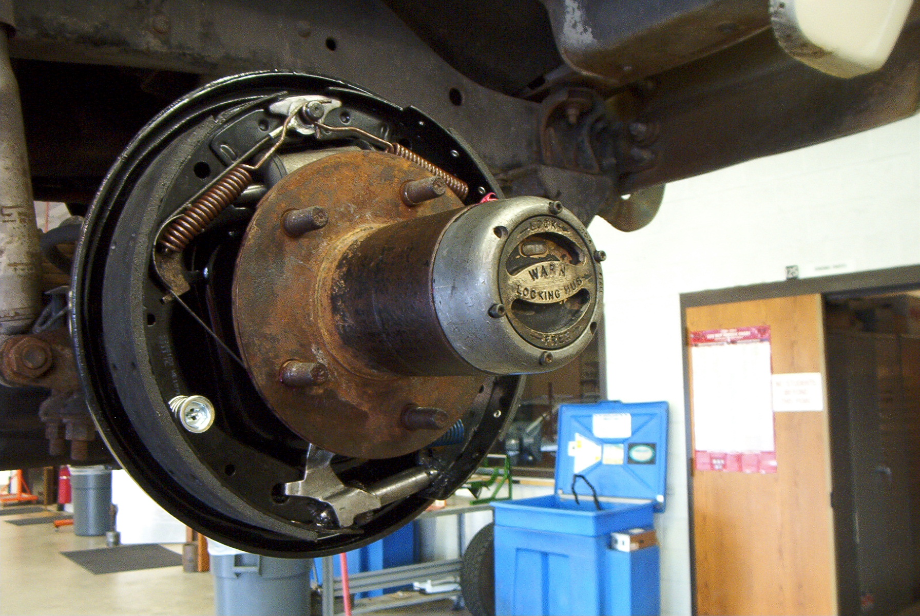 |
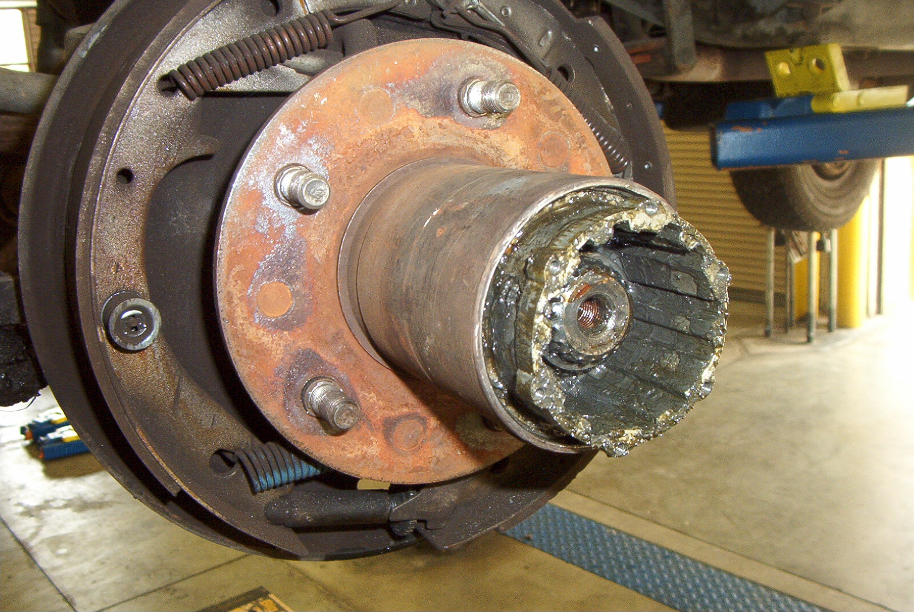
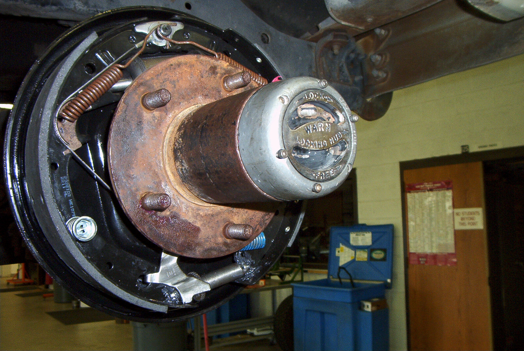
This is how it will look prior to starting
any repairs.
Start the repair by removing the locking hub mechanism. On this particular model hub there are six Allen head screws holding the locking mechanism to the rest of the hub body. Use a 7/64" Allen wrench to remove them. Once the screws are out simply pull on the cap. It may require a light tapping with a hammer or mallet. Be sure not to damage the cap, unless you are replacing the locking hub as well. |
 |
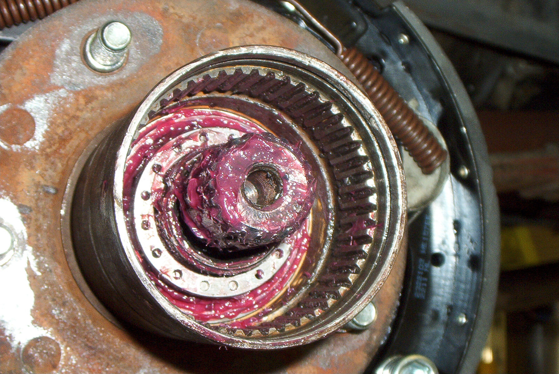
This is how it will look after removing
the hub locking mechanism. The next step is to remove the locking hub body. To do this, you must first remove two retaining rings. One is inside the hub behind the axle splines, which is removed by using the retaining ring pliers. You will have to clean out the hub with brake cleaner in order to see where to put the pliers. The second ring is in a groove machined into the wheel hub interior. It is very hard to see unless you're looking for it, and even then it's difficult. There is a small section of about half an inch between the two ends of the ring. This is what you're looking for. Once you find that section, use a small chisel and a hammer to get under the ring, propping it up, and then pull it out using a set of picks. This requires a little finesse, but is fairly easily accomplished. Be sure to wear safety glasses when doing this, as the ring can pop out of the groove and shoot toward your face. When both rings are out, pull on the hub body to remove it from the wheel hub. Again, it may require a light tapping with a hammer or mallet. |
 |
After the locking hub has been removed,
the next step is removing the axle spindle lock nuts. This
requires the special tool and a 1/2" drive breaker bar.
DO NOT USE AN IMPACT WRENCH. There are four prongs on the socket which fit into four notches in the lock nut. You must seat these notches, then loosen the nut. With my socket it also requires me to push against the nut so as not to pop out of the notches. Lisle Tools makes a socket which supposedly reduces or eliminates slipping of the socket. After the first lock nut has been removed from the spindle, there is a washer that must be removed by using picks. Remove that, then repeat the loosening procedure on the second lock nut. |
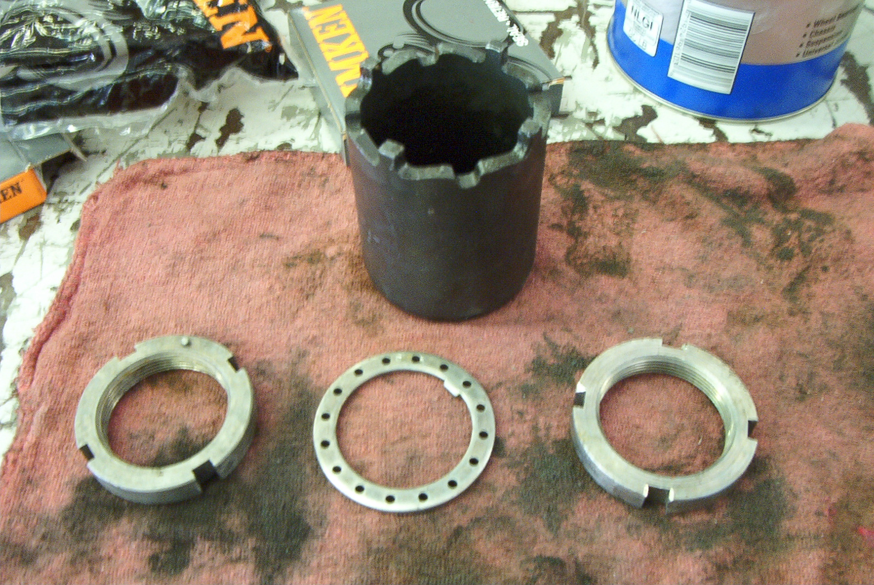 |
This is the socket, lock nuts, and washer. Note the key and holes drilled in the washer, and a pin in one nut. The key fits in a machined keyway in the spindle, and one hole fits over the pin. When installing the lock nuts and washer, the first nut is seated as far as possible against the hub bearing while the washer is installed. If a washer hole does not fit over the pin, simply adjust the nut until the washer is flush against it. |
 |
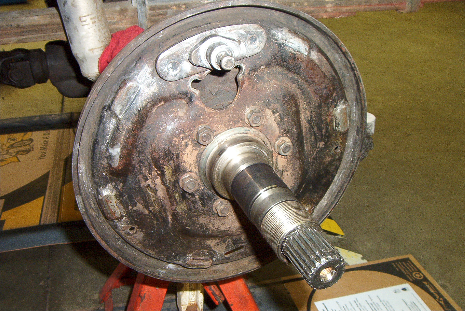
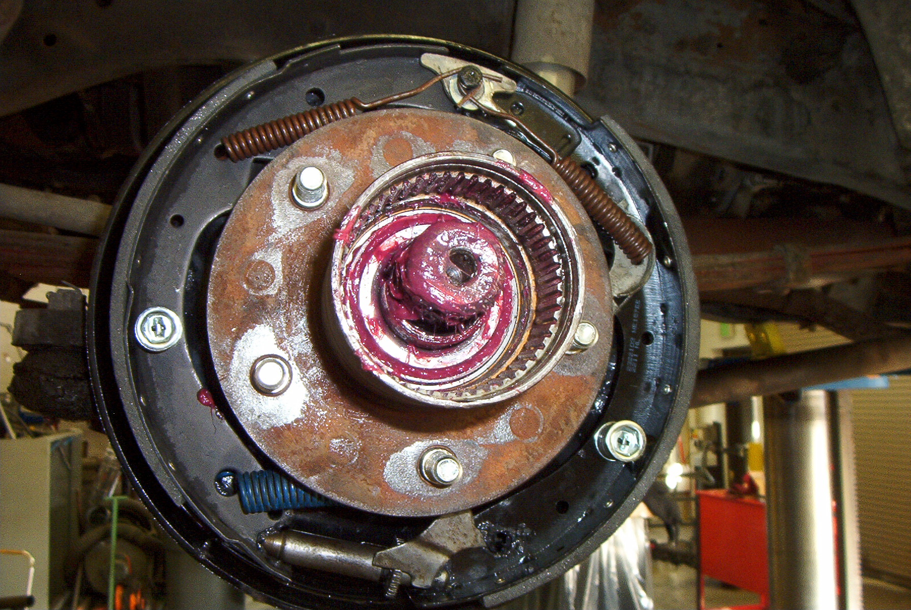
Once the lock nuts and washer have been
removed, the hub can be pulled off the spindle. Again, it may
require a light tapping with a hammer or mallet. This is what it
looks like after the hub is removed.
At this point the brakes can be disassembled. Remember to wear safety glasses when removing the brake springs, as they are under quite a bit of tension. |
 |
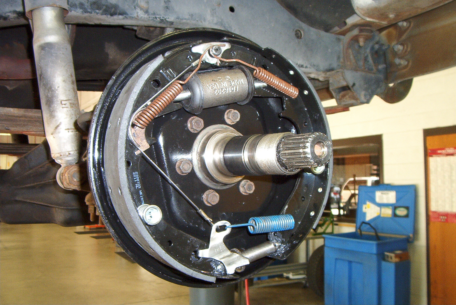
Now that the brakes have been disassembled, only the backing plate remains. To remove it, loosen and remove the six nuts holding it to the spindle. These will most likely be quite tight as the backing plate is seldom removed, so squirt a little penetrating oil on them before attempting to loosen them. Or use an impact wrench with a 9/16" socket. Your call. |
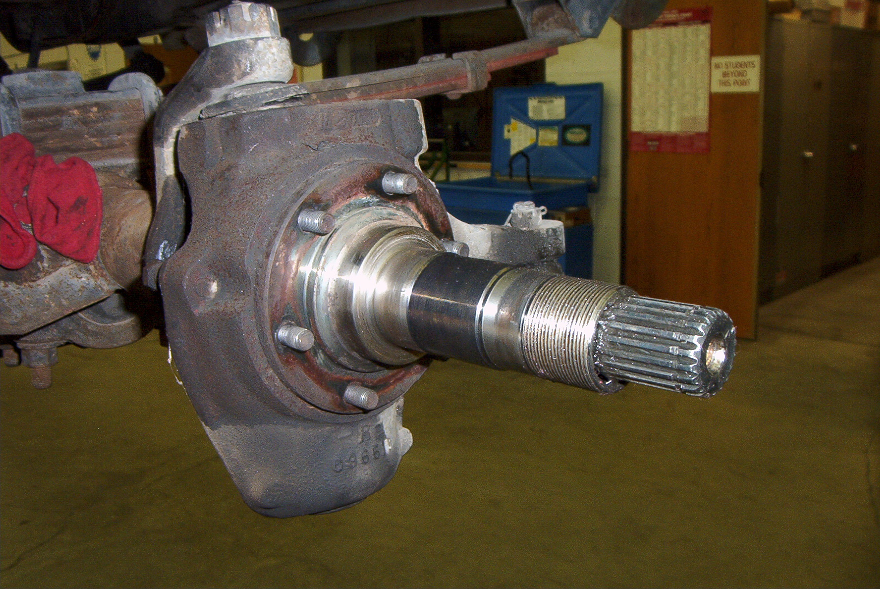 |
A photo of the steering knuckle and the spindle. |
 |
This is the backing plate after it has been bead blasted. |
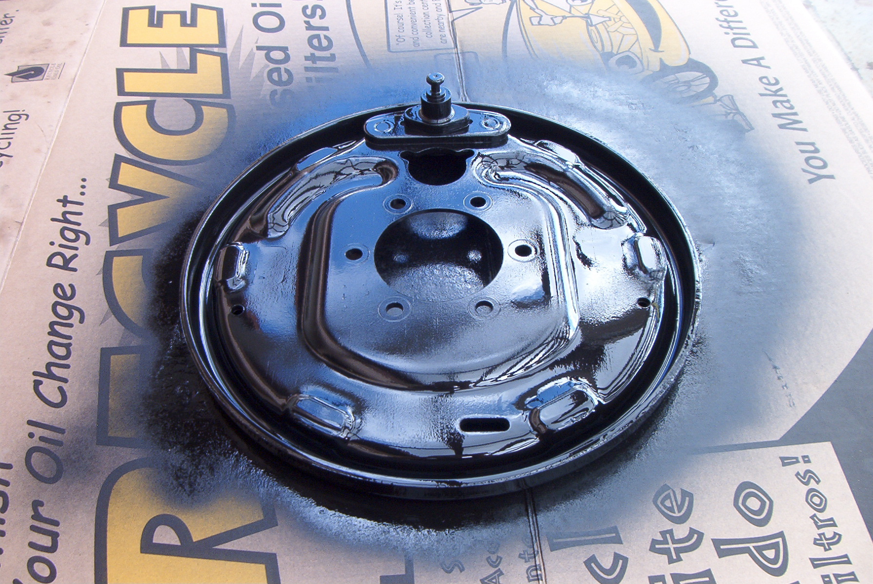 |
After painting with Rustoleum semi-gloss black paint. |
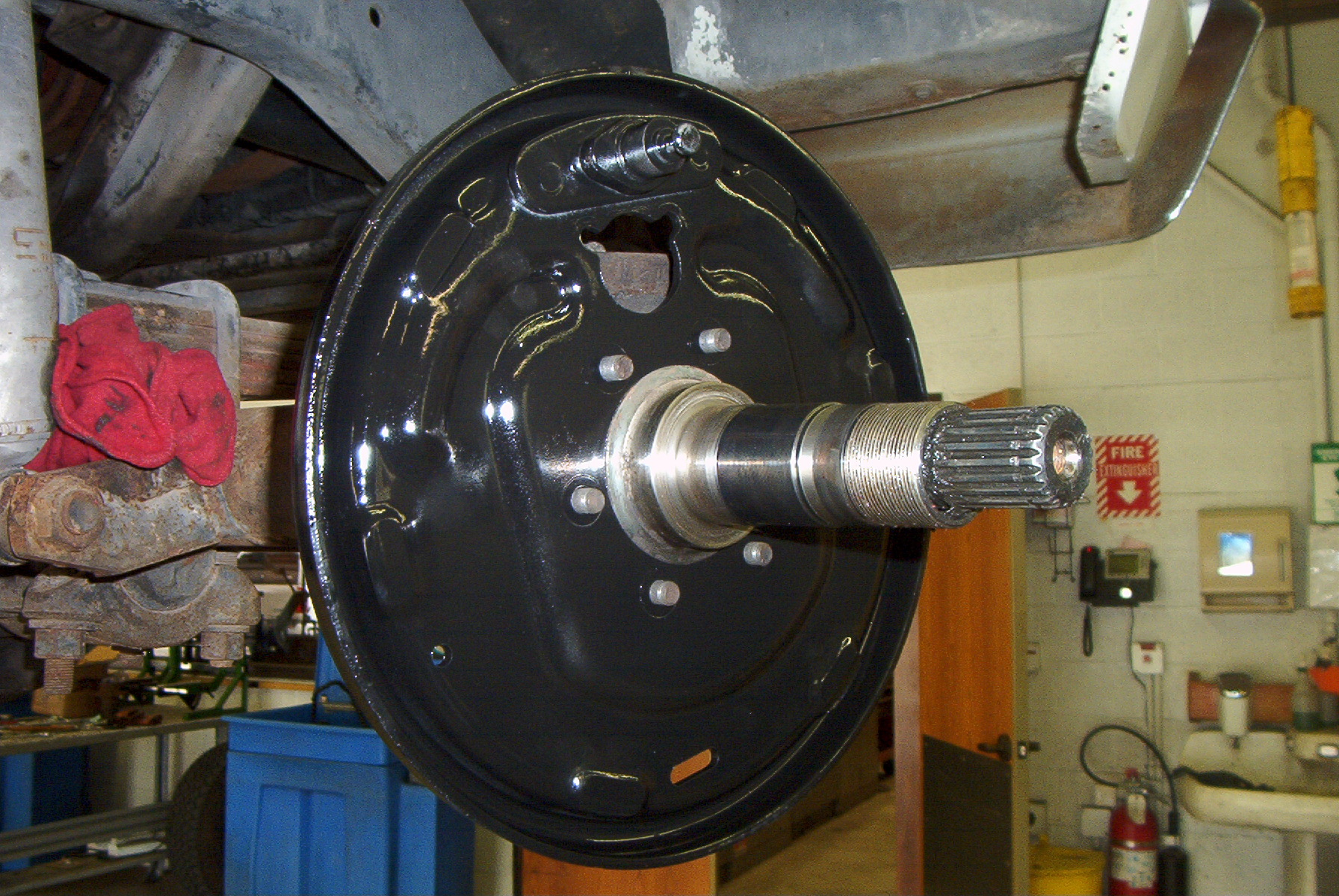 |
The paint has dried, and the backing plate reinstalled on the spindle. Reinstall the nuts, and torque to 30 ft/lb. |
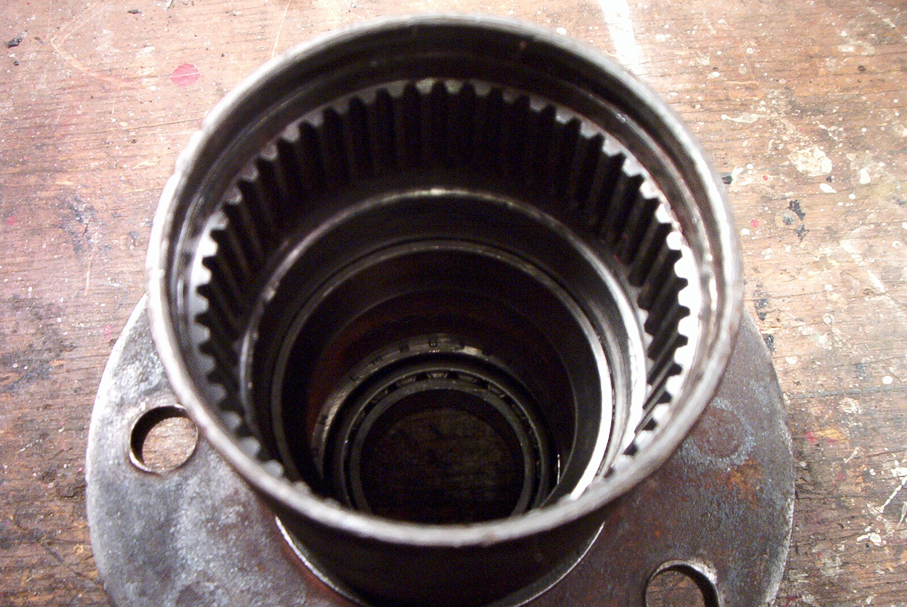 |
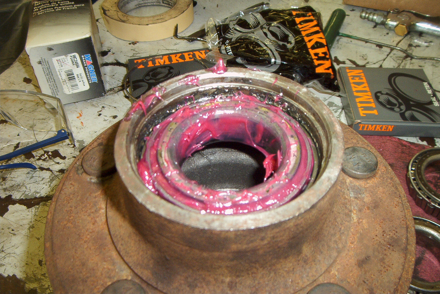
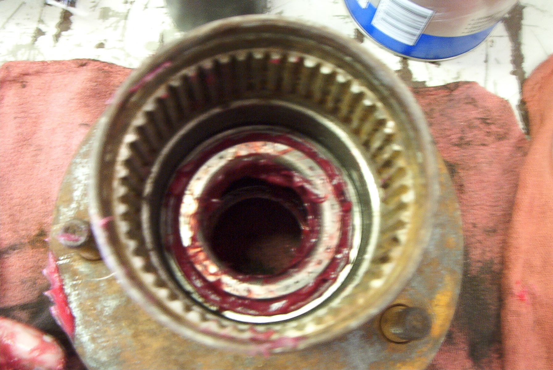
Here is the hub fully removed from the
spindle. While not entirely lit, it is possible to see the inner
bearing race, and the rear bearing. The bearing is held in place
by a wheel hub seal. Simply use a punch to drive this out, and
remove the bearing. Inspect both bearing races for damage.
If they are in good shape, drive them out using the bearing driver, or
use the punch being careful not to damage them. If they are
damaged, replace them. To install, simply hammer them in using the driver or punch until they sit flush against the steps machined in the hub. |
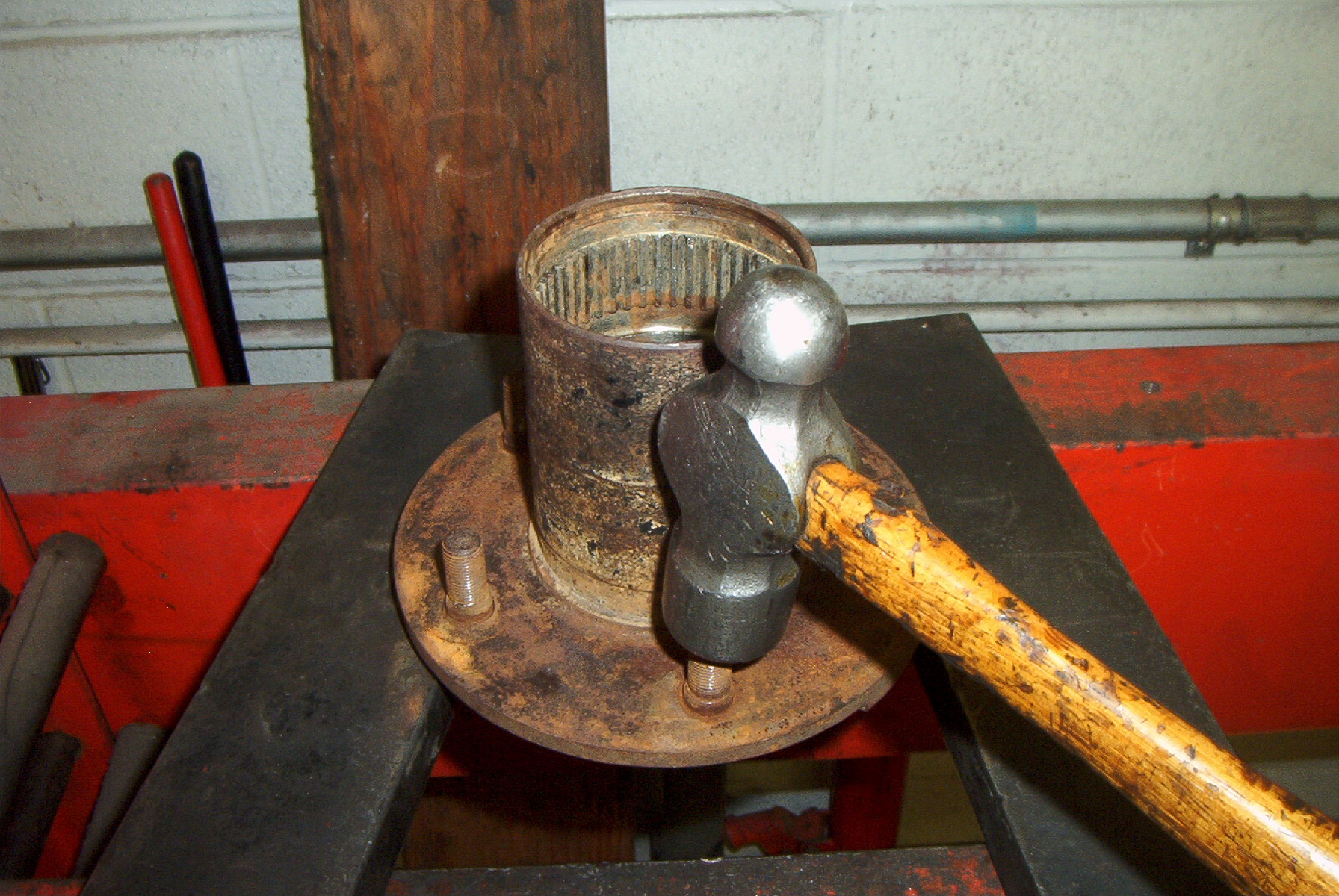 |
Since these wheel hubs are no longer available new, junkyard units are the only source. These will most likely have the wheel studs still pressed into the hub. On my replacement unit I simply cleaned them up using a 1/2-24NF die, but I also replaced the studs on the opposite hub because they were loose. To replace the studs, position the hub between two supports as shown, then hammer the stud out. |
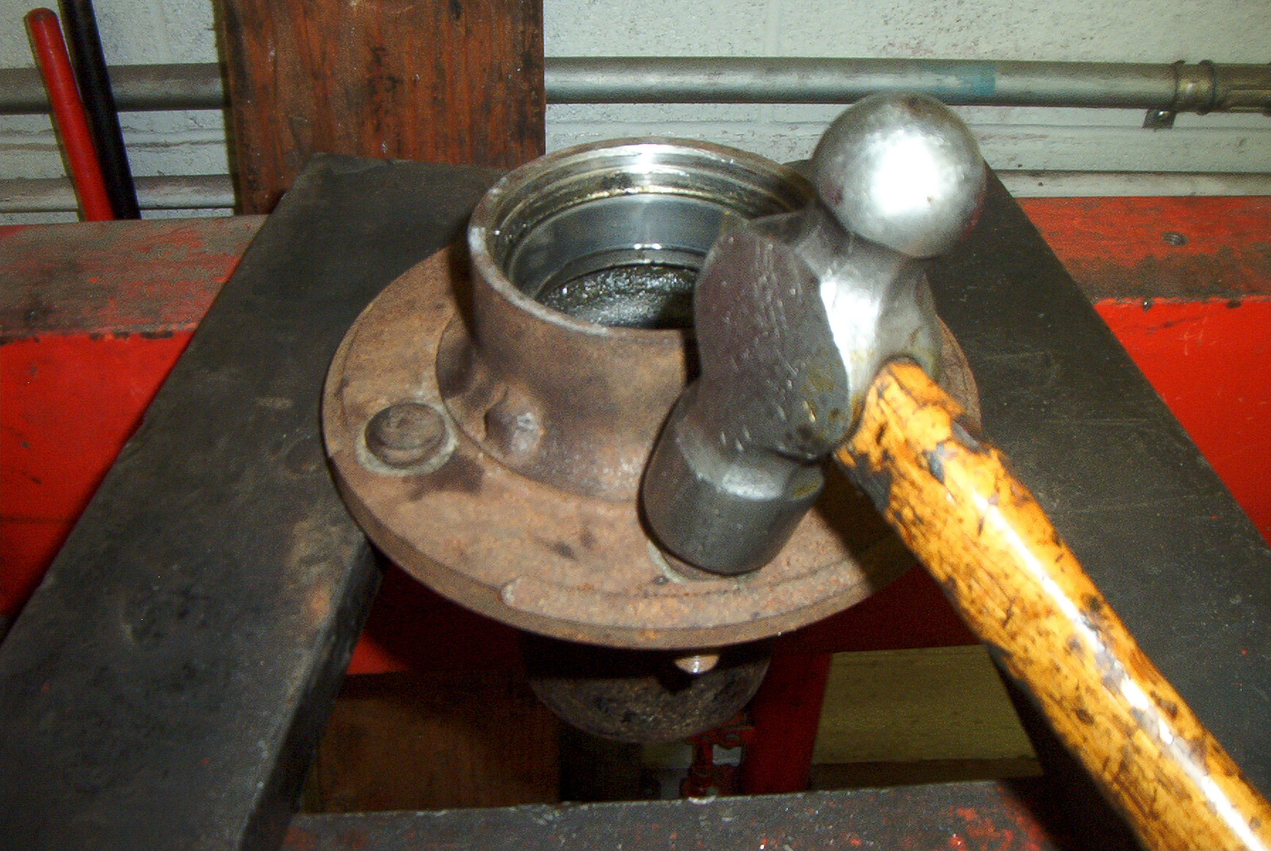 |
To install, flip the hub over, position the stud, and hammer it in until it sits flush. This picture also shows the rear bearing race properly seated. |
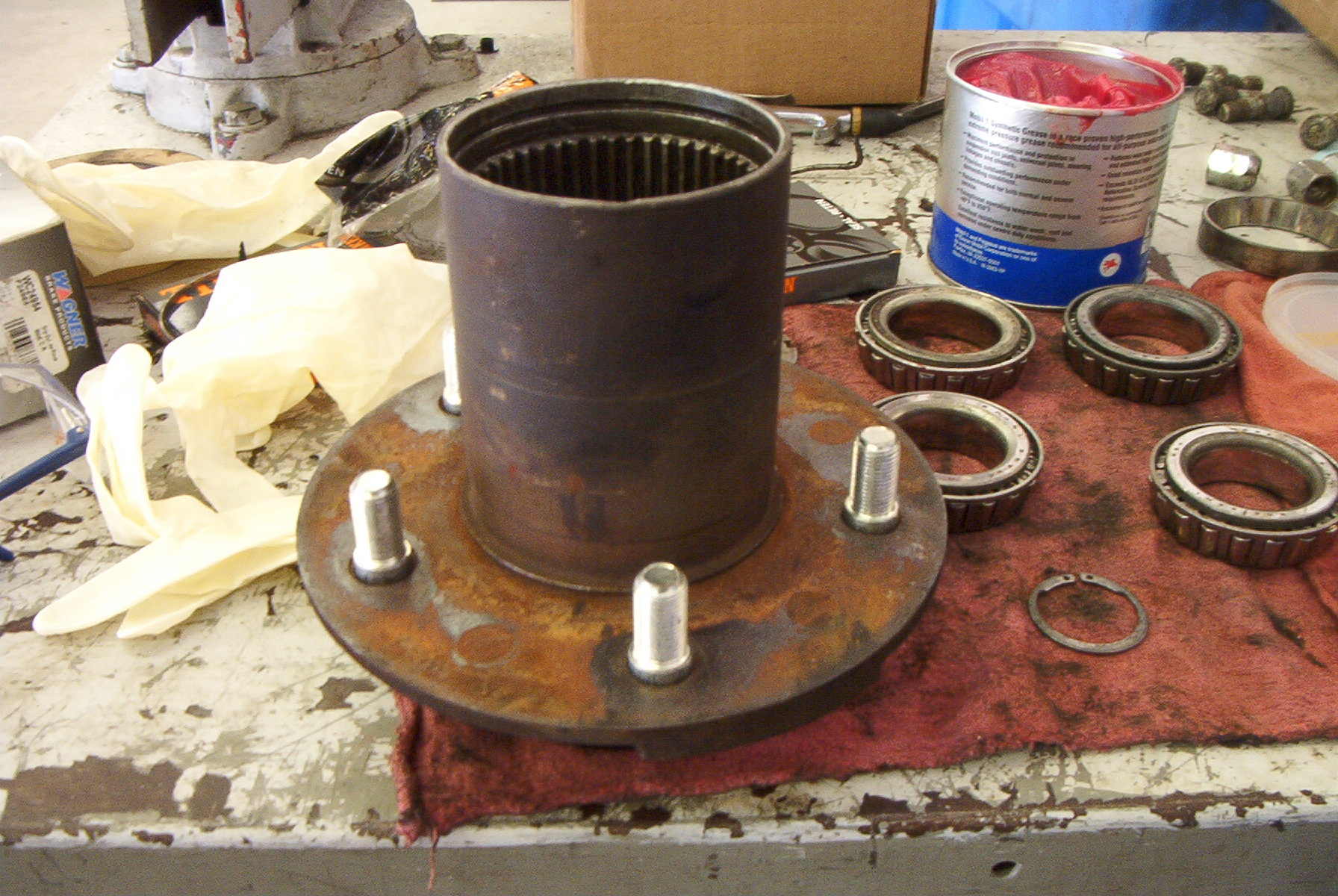 |
The hub with new studs installed. Also note the retaining ring groove in the upper portion of the hub. |
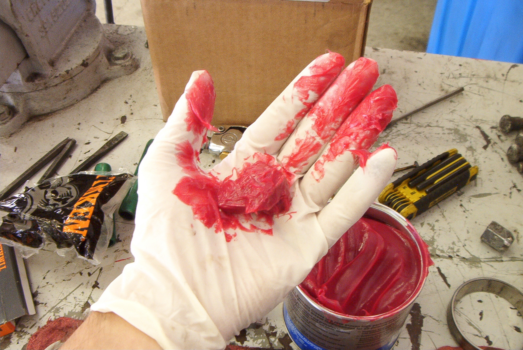 |
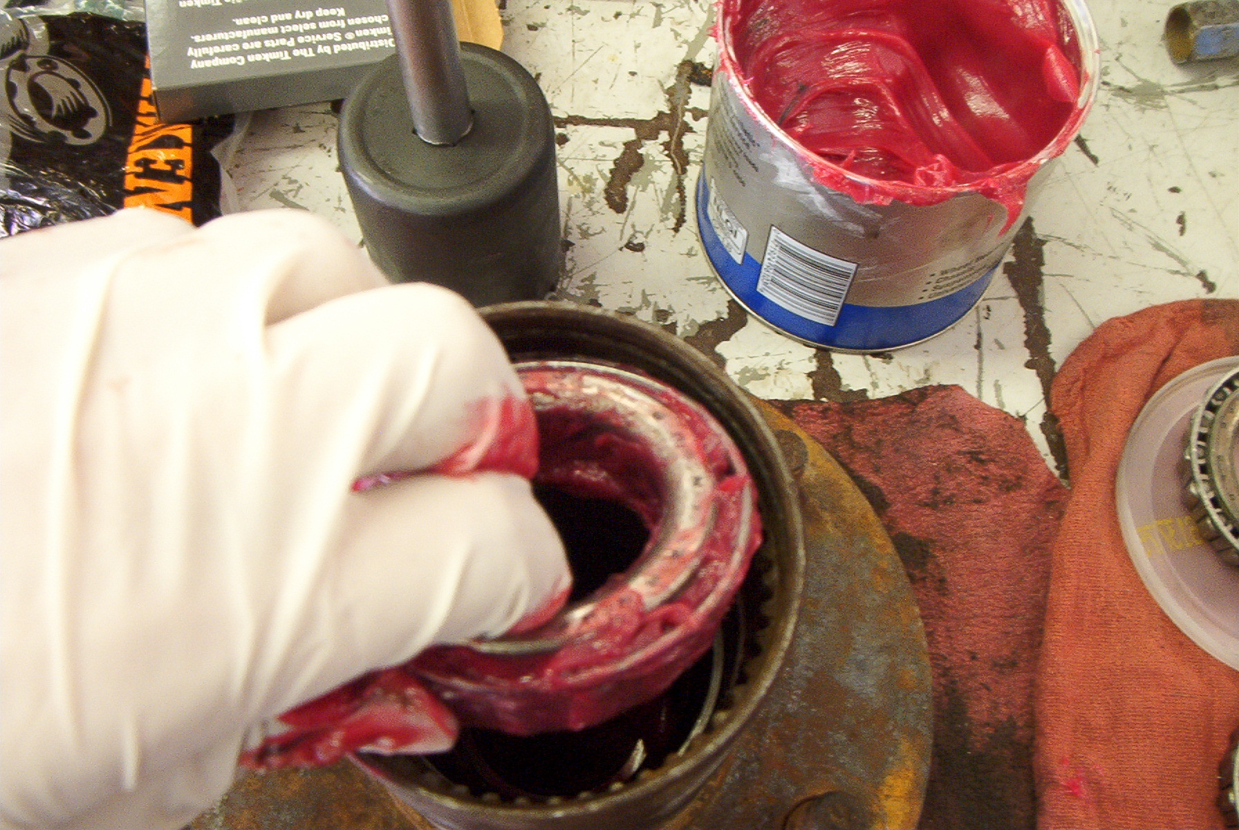
Now it's time to grease the bearings.
However, prior to greasing, you must inspect the bearings and be sure
they are suitable for reuse. My bearings were in good shape, so I
cleaned them in a solvent tank, then repacked them. To repack, get a good dollop of grease in one hand. The amount shown at left is a good starting point. |
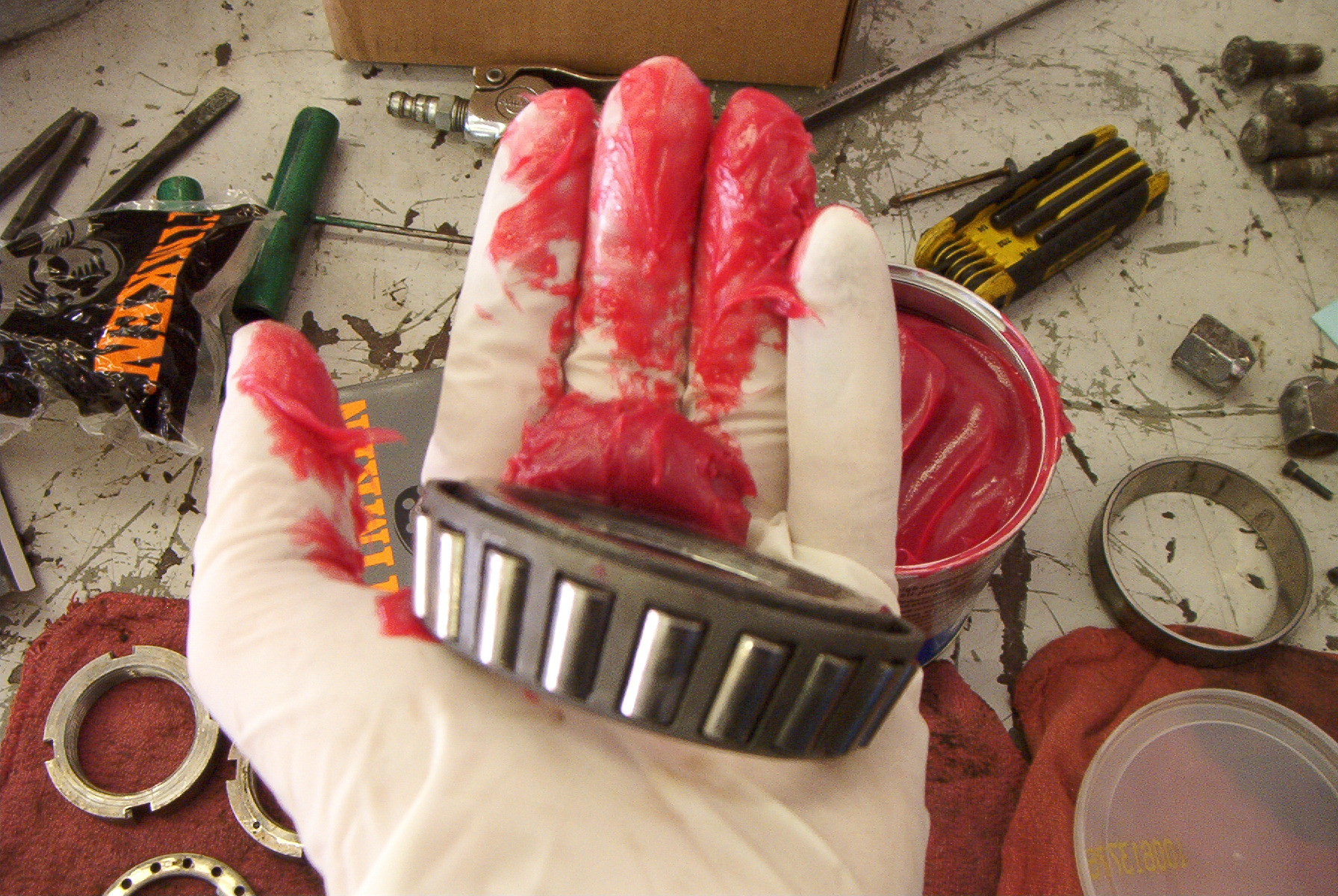 |
This shows how the bearing should be
oriented in the packing hand. With your other hand, insert two
fingers through the bearing and close your hand into a fist. Then
press the bearing into the grease with a digging motion. You want
to see fresh clean grease flowing over the rollers and up through the
back of the bearing. When only new grease comes through, the
bearing is packed. You may also use a bearing packer. I don't know how well they work, as I've never used one. |
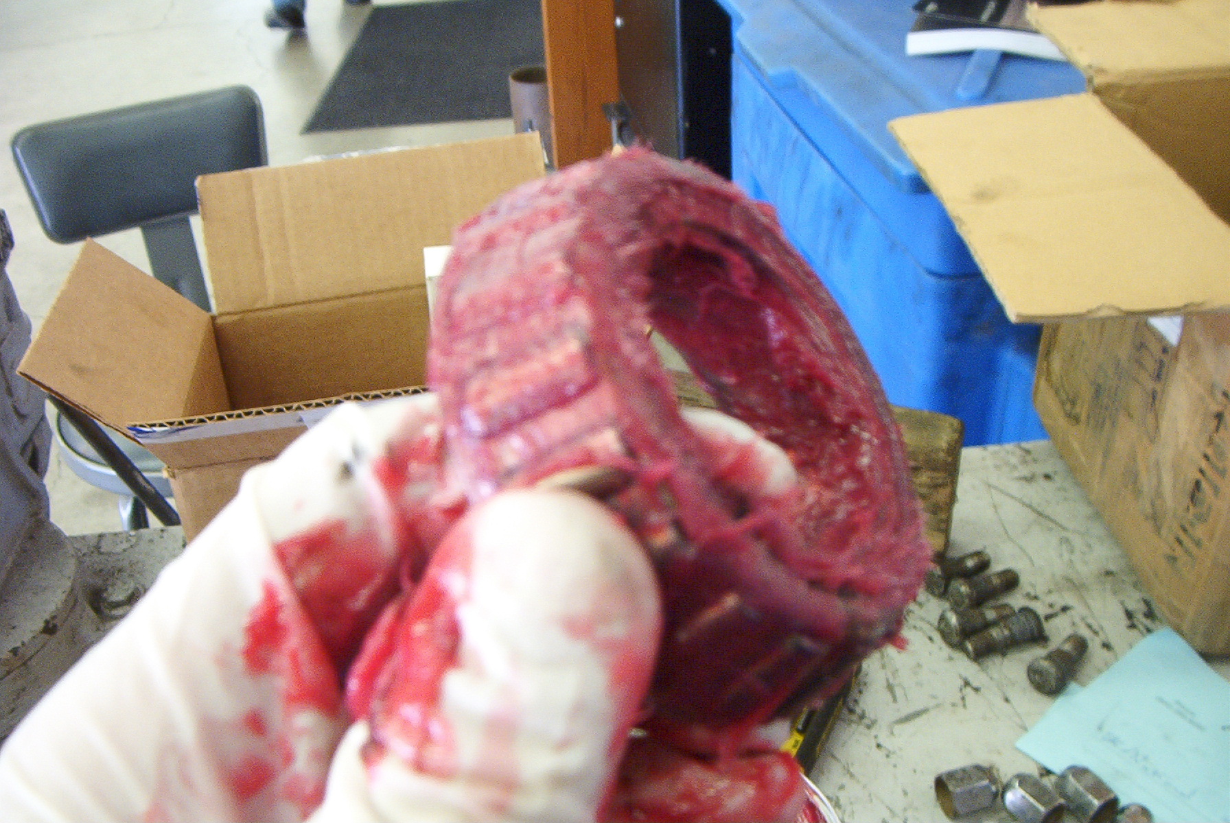 |
This is what a properly packed bearing should look like. Note the large amount of grease inside the bearing itself. |
 |
Set the bearing in the race. The rear bearing must be done first, as it is retained by a seal. |
 |
Here is the seal fully pressed into the
hub. Photos of the actual seating procedure were not taken. To seat the seal, set it in place as best as possible. Be sure to face the seal lip inwards. Get it started by pushing on it with your hands, then use the seal driver to seat it. If not using a seal driver, lay the 2x4 across the seal, then just hammer it until it sits flush against the hub. If done properly the bearing should spin freely in the race, but also have about 1/4 to 1/2 inch of play between its top and the seal. |
 |
Next, flip the hub over and drop in the inner bearing. |
 |
This is how the inner bearing should sit. |
 |
After reassembling and bleeding the
brakes, reinstall the hub. To seat the bearings, the first lock
nut is screwed onto the spindle until it contacts the bearing, then it
is tightened to 50 ft/lbs while spinning the hub in both directions.
After it is torqued, back it off one quarter to one third of a turn,
then install the washer. Adjust the nut as necessary to make sure
the washer sits flush. After the washer is properly seated, install the second lock nut. This is tightened to 125 ft/lbs. Spin the hub. If there is any catching, grinding, or suspicious noises, it must be removed again and the bearings inspected. These bearings take a great deal of load, and must be free of any dirt or contaminants. Remember, YOU are riding on these bearings. After insuring a free rotation, I like to add a little more grease to the hub interior, and inside the locking hub. I figure the more grease, the less space for water to displace. To reinstall the locking hub, simply reverse the removal procedure. When installing the locking mechanism cap, torque the Allen screws to 30 in/lbs, or failing that, snug.
|
 |
The job is finished. Pre-adjust the brakes, reinstall the wheel, and torque the lug nuts to 80-90 ft/lbs. Then adjust the brakes until there is a slight drag felt when rotating the wheel. When a drag is felt, back off the adjuster until there is no drag. Do the same for each wheel. |
Torque Specifications
| Locking Hub Screws | 30 in/lb |
| Backing Plate Nuts | 30 ft/lb |
| Inner Spindle Lock Nut | 50 ft/lb, then back off 1/4 to 1/3 turn |
| Outer Spindle Lock Nut | 125 ft/lb |
| Lug Nuts | 80-90 ft/lb |