 |
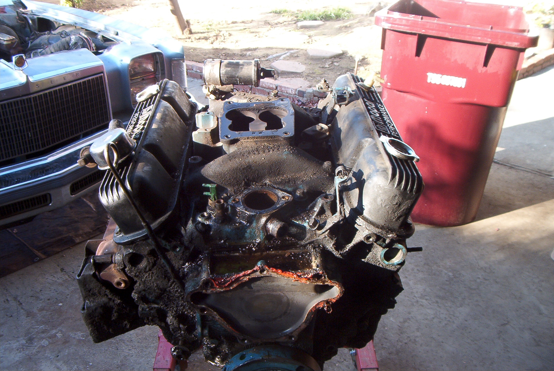
After the A/C compressor, smog pump, water pump, crankshaft pulley, carburetor, distributor, and vacuum lines have been removed. |
 |
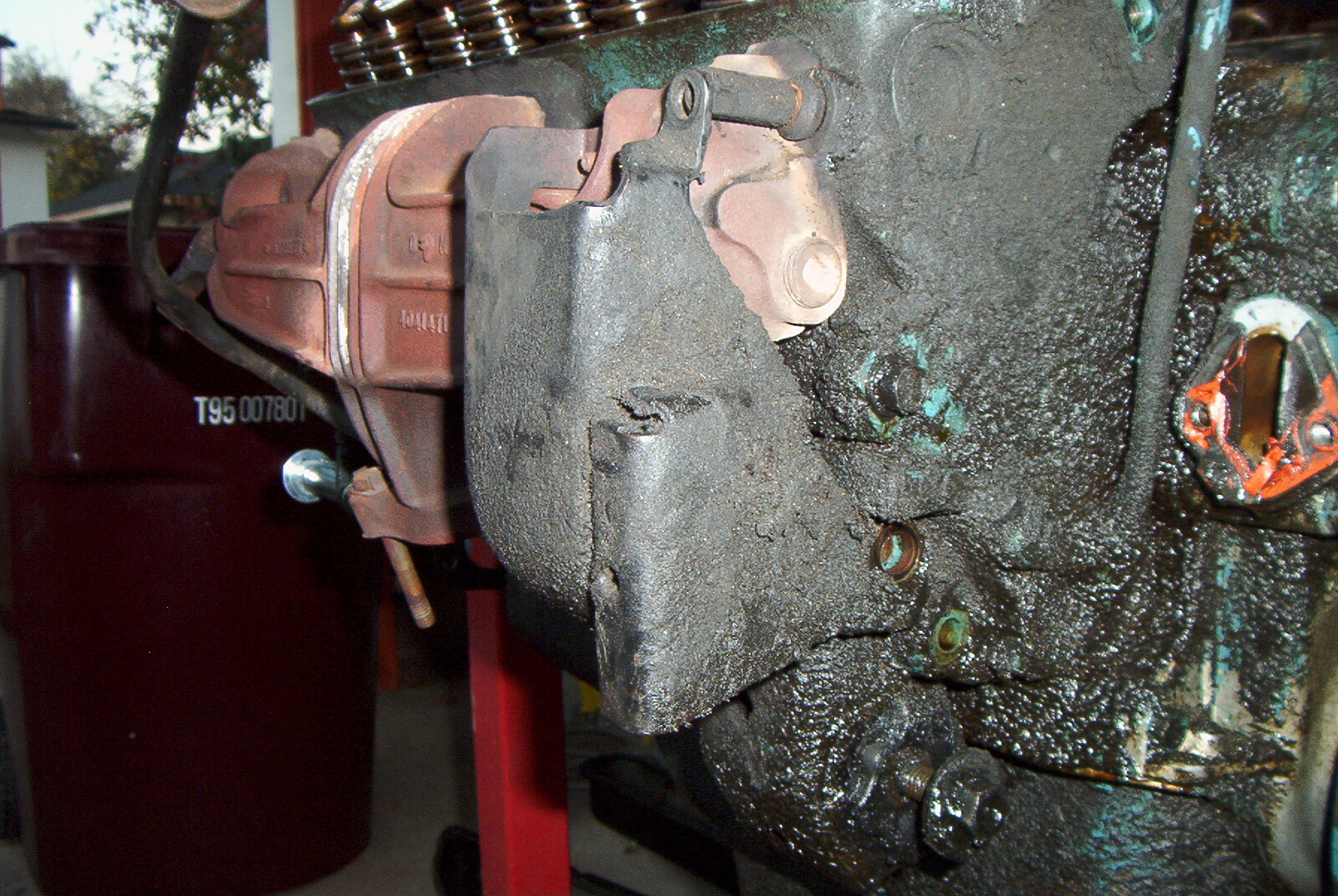
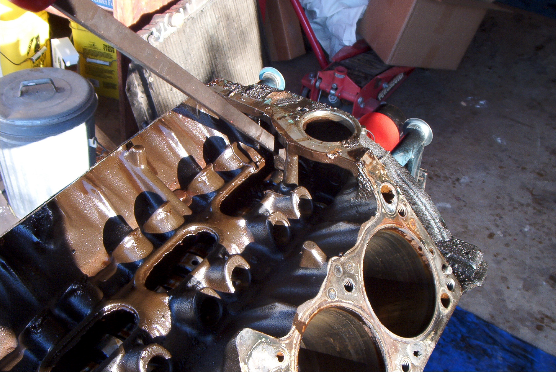
The back of the motor. The hole is where the distributor goes. The golden object is the electrical oil pressure sending unit. |
 |
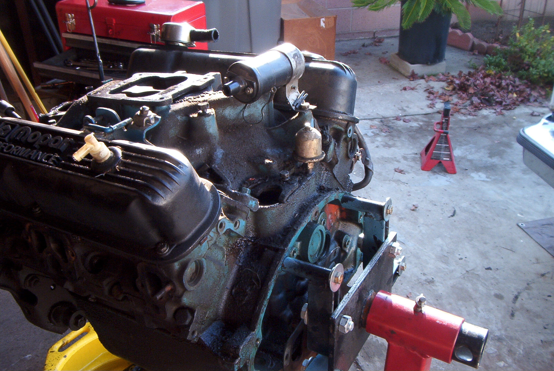
The EGR valve and driver side valve cover have been removed. |
 |
Both valve covers and the intake manifold have been removed. |
 |
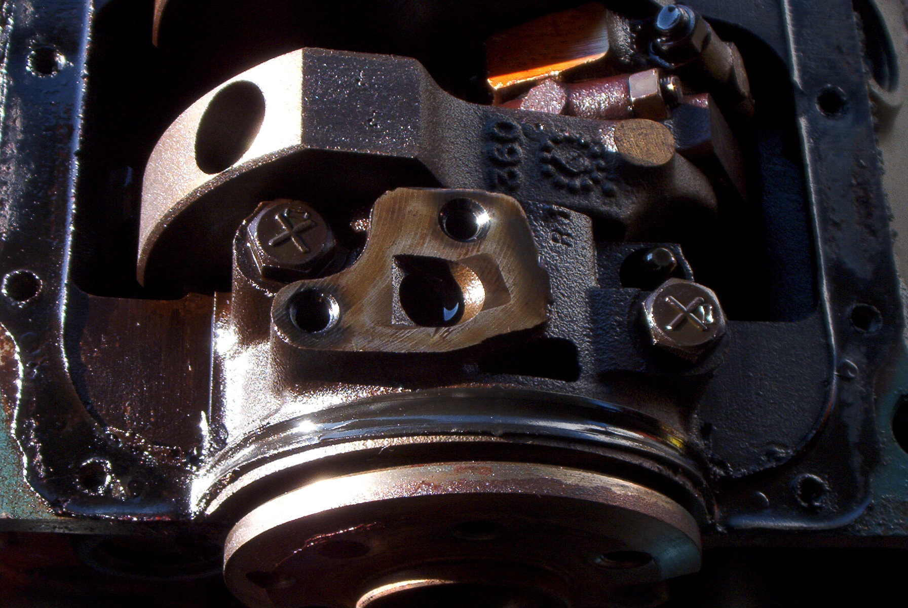
How an unknown bracket is mounted. |
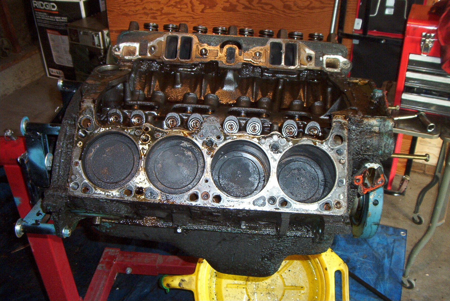 |
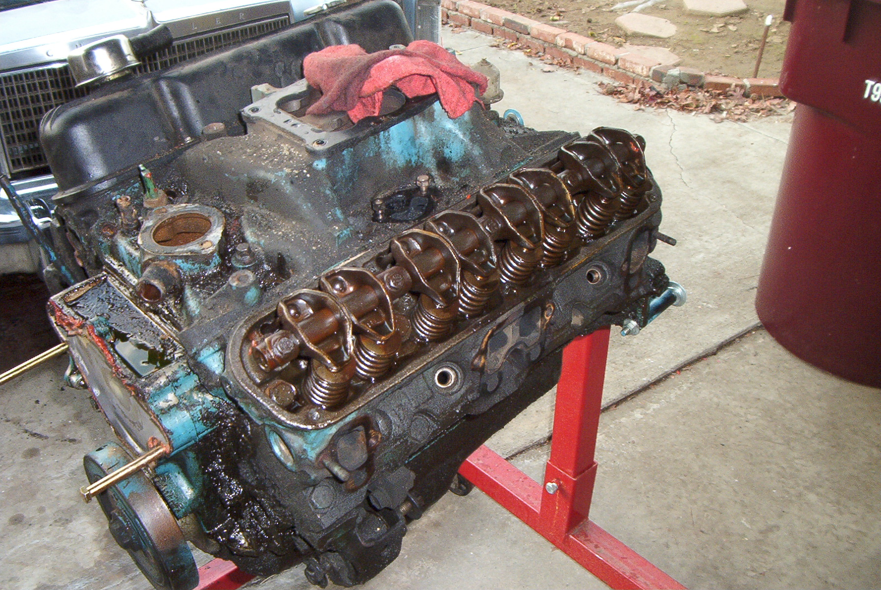
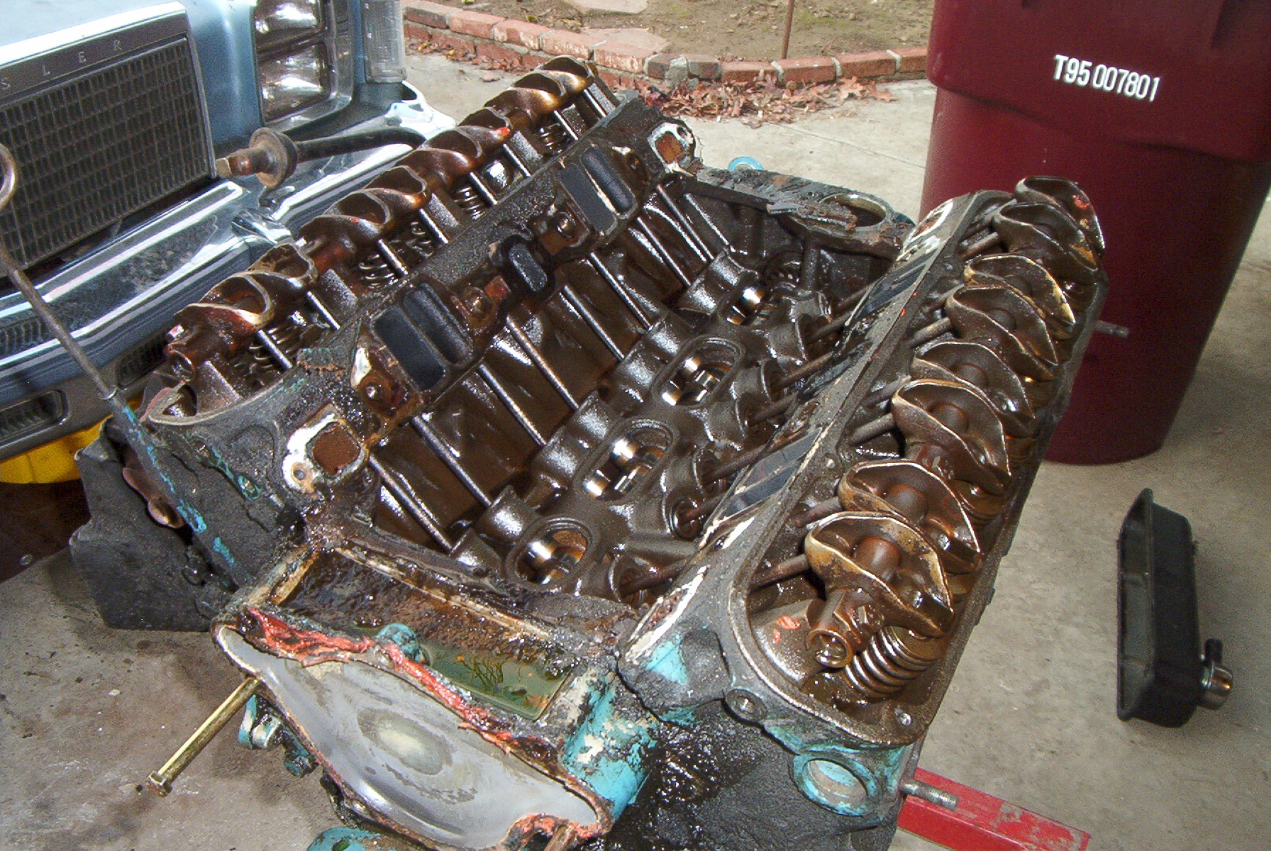
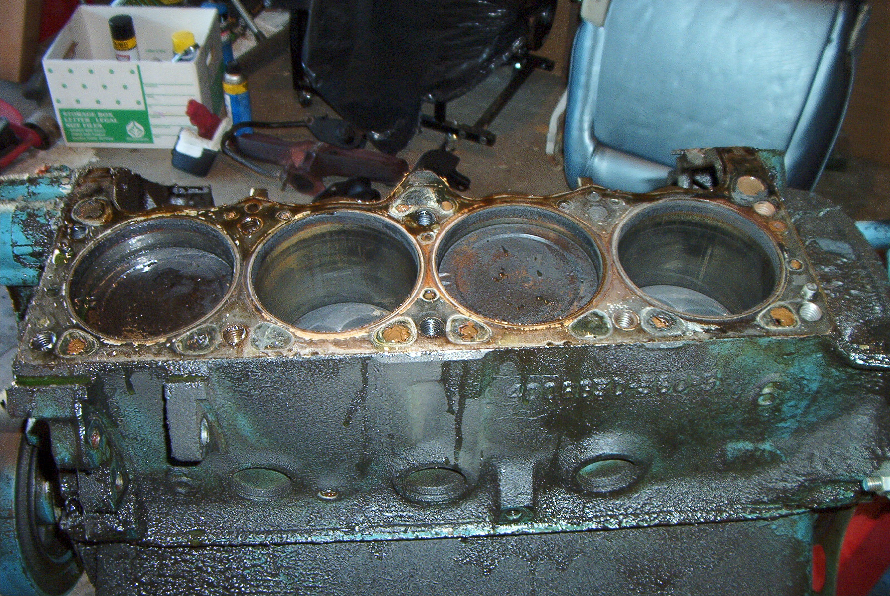
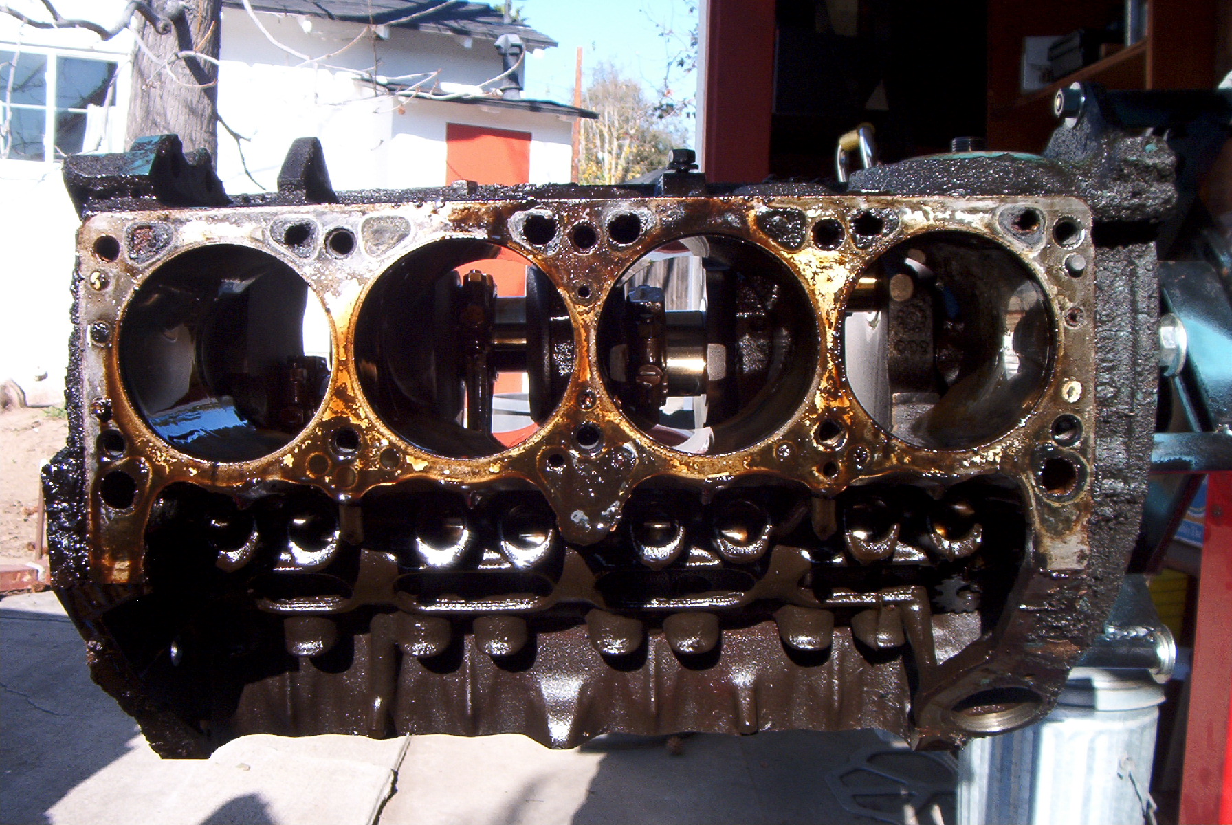
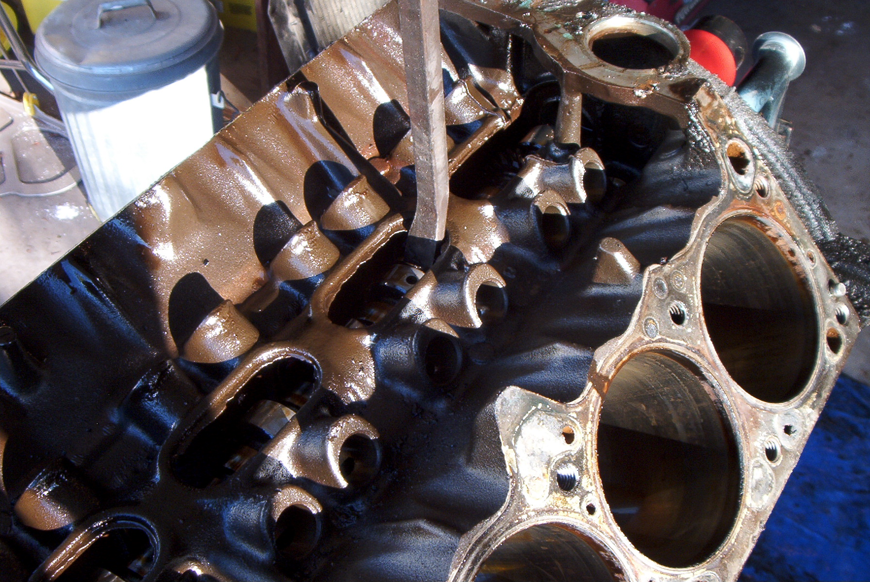
Heads have been removed. Right cylinder bank shown. |
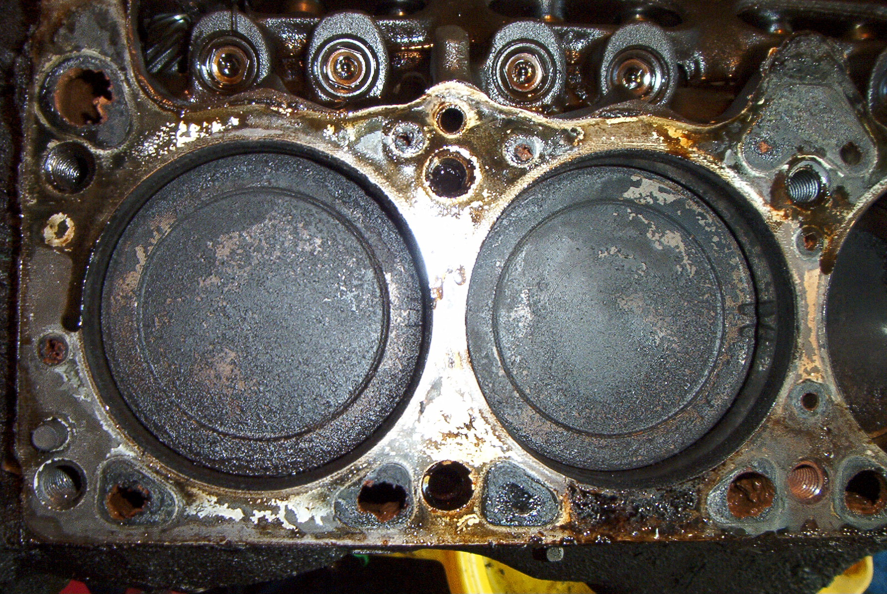 |
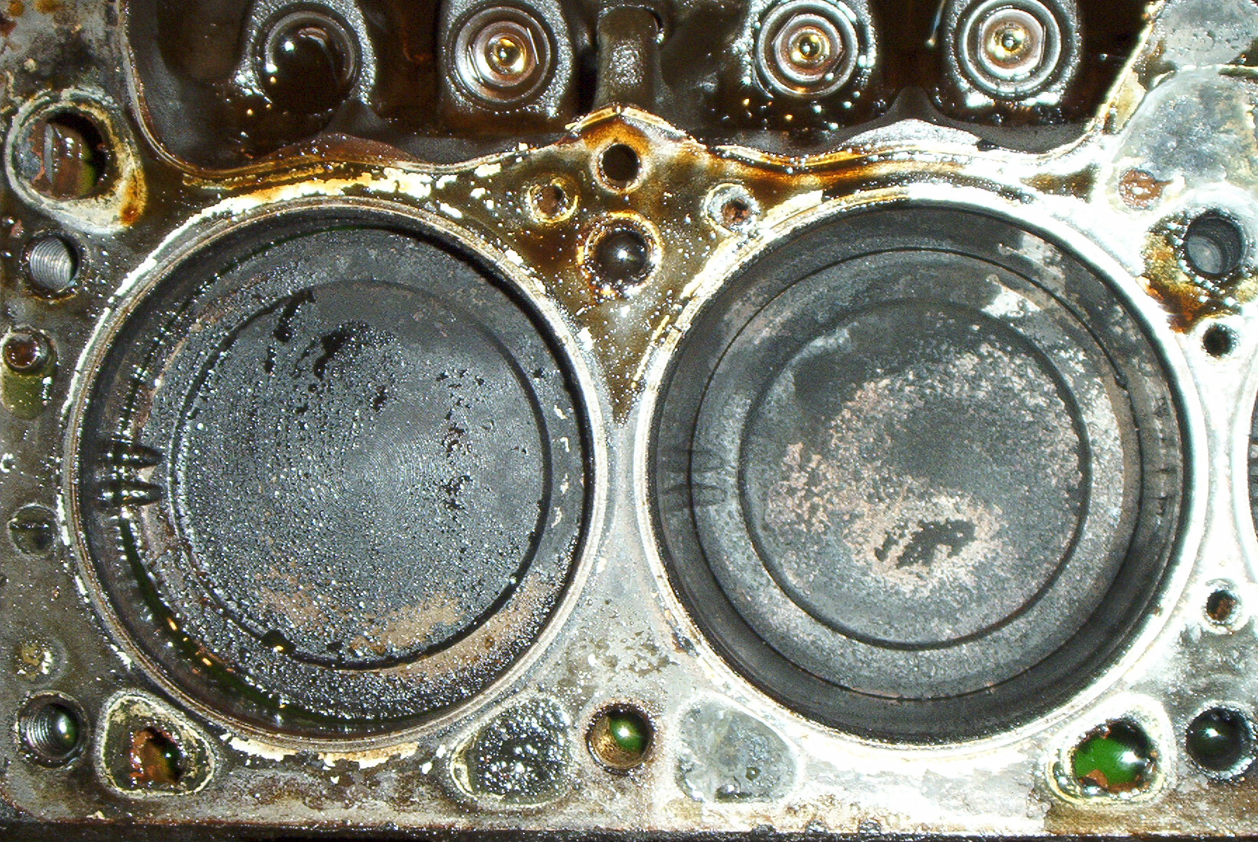
Cylinders 8 and 6. Not much carbon build-up on the pistons, considering the age of the engine. |
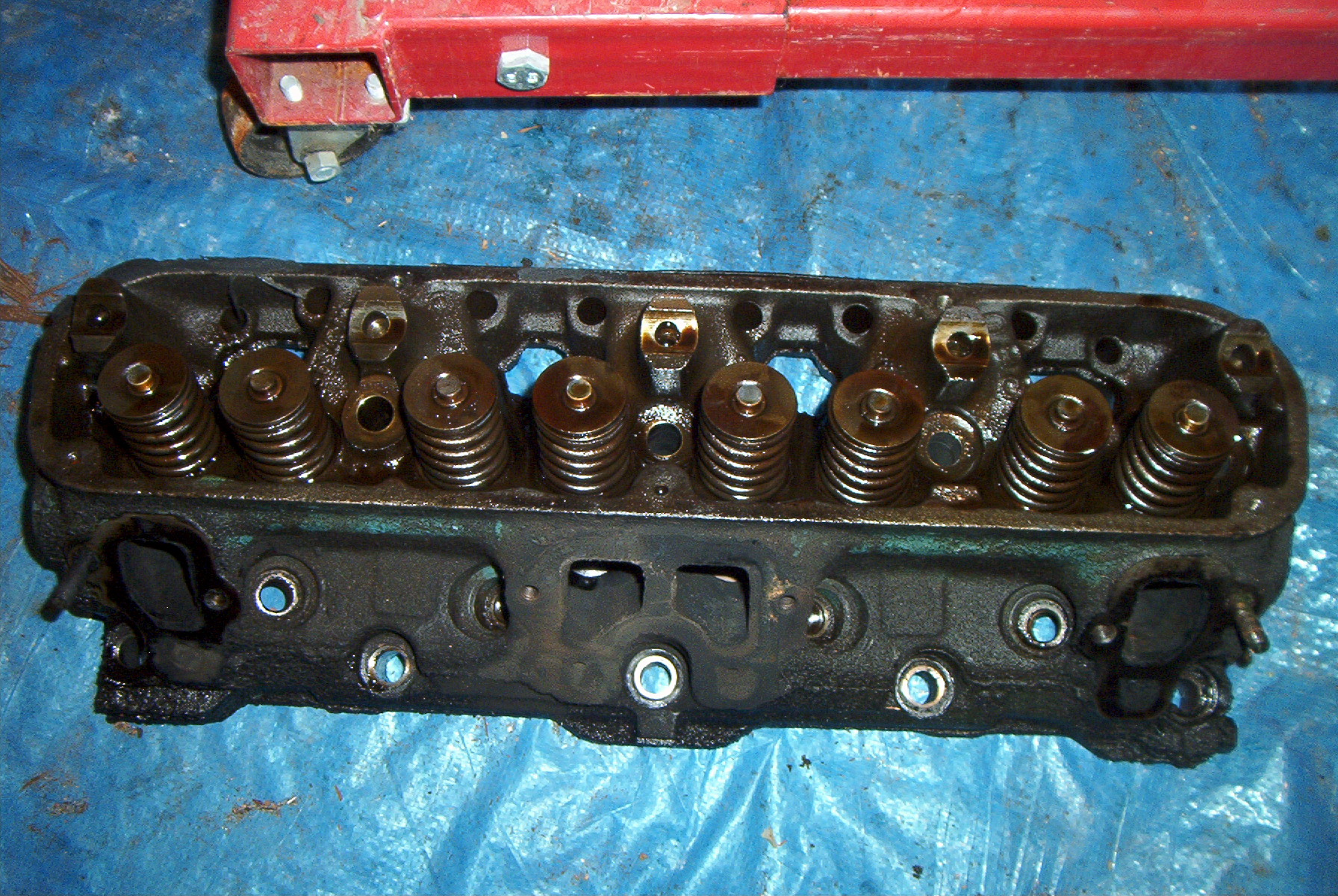 |
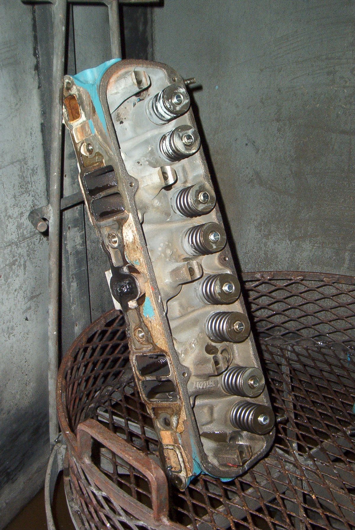
A cylinder head. |
 |
Left cylinder bank. |
 |
Cylinders 1 and 3. Not much carbon build-up on these as well. |
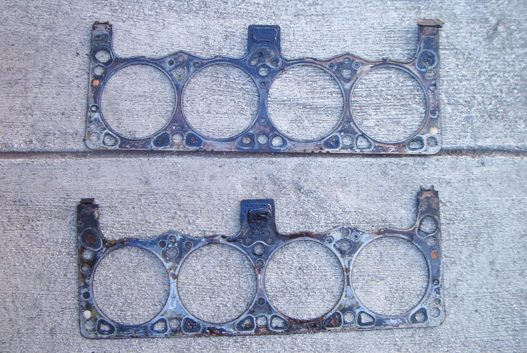 |
The original steel gaskets, still in decent shape for being thirty years old. |
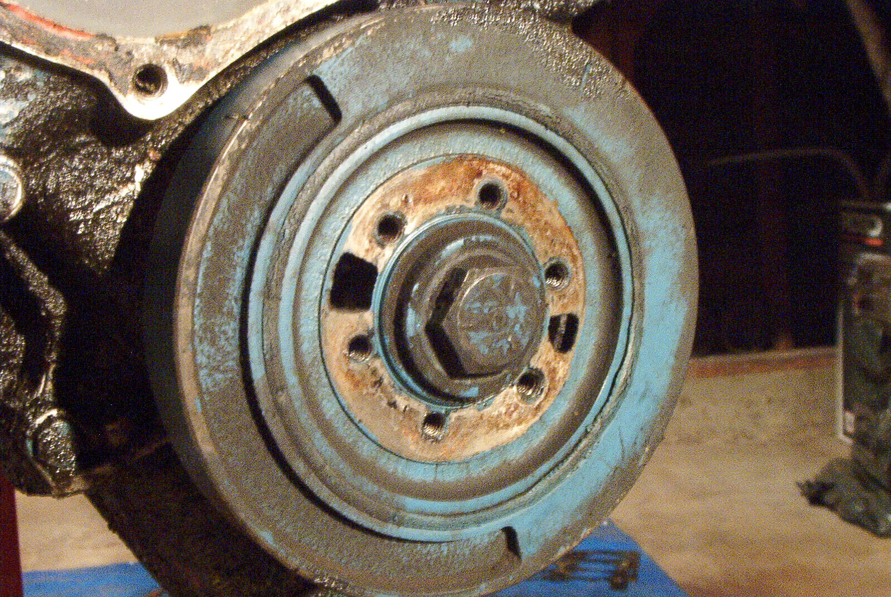 |
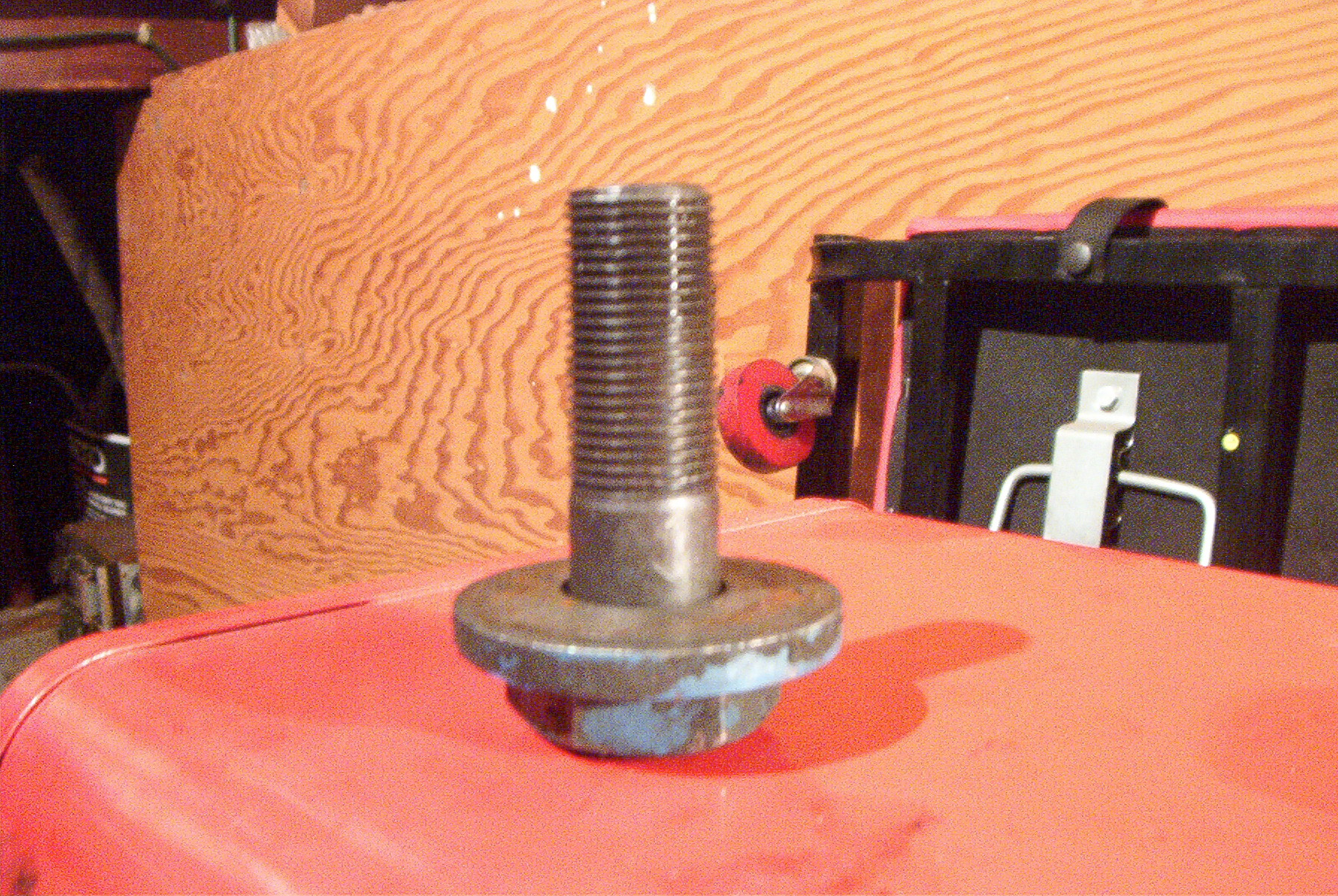
The harmonic balancer. This absorbs the natural harmonic vibrations in the crankshaft, caused by each firing every ninety degrees. Without this, the motor would literally vibrate itself apart. It's held on with a 3/4" fine thread bolt, torqued to over one hundred ft/lbs. |
 |
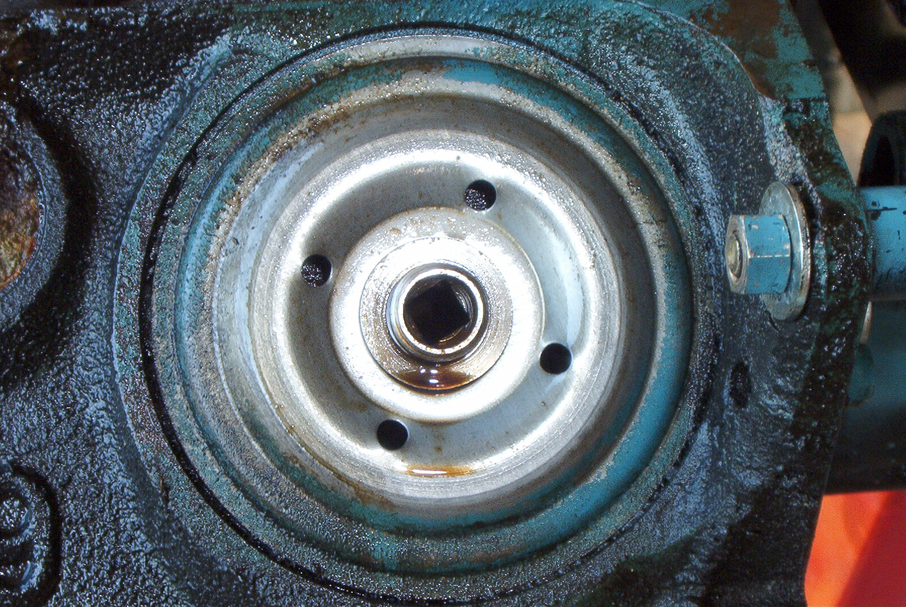
The harmonic balancer bolt is removed. |
 |
The oil filter mount. |
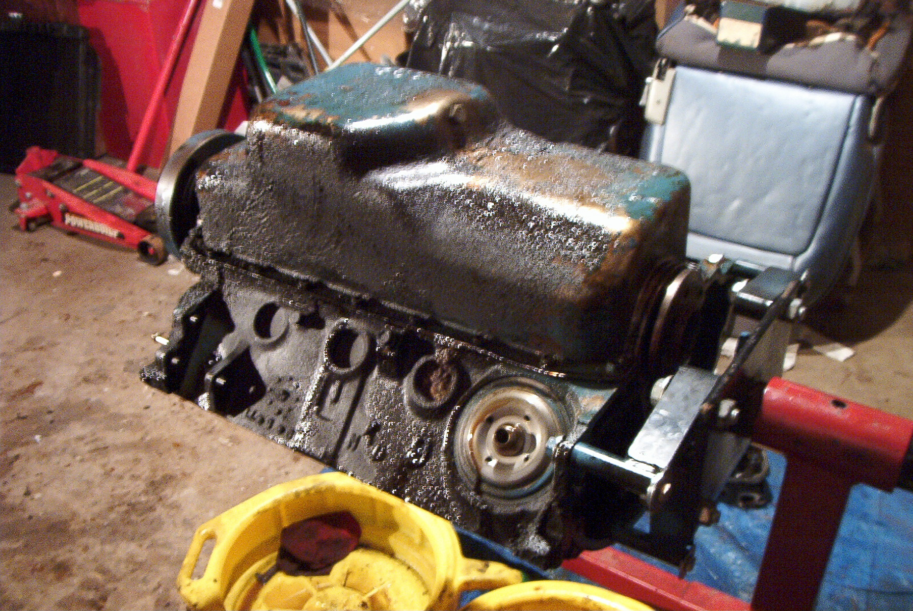 |
The block and pan. Again note the massive amount of road grime and caked on oil. |
 |
The oil pan is removed. |
 |
Another view. |
|
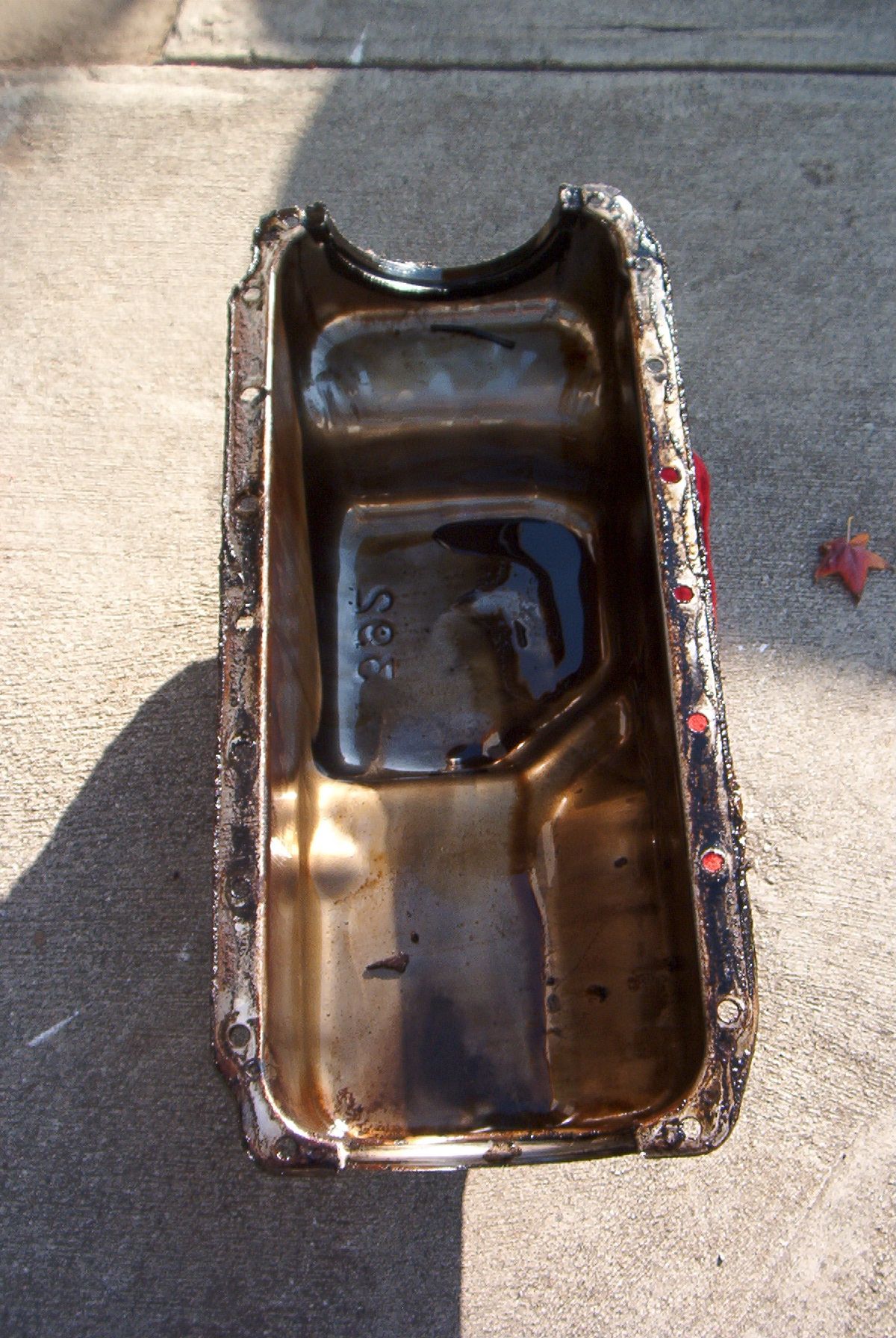
|
The oil pan. It was surprisingly clean inside, with no metal fragments, or chunks of block or bearing. Just old dirty oil. |
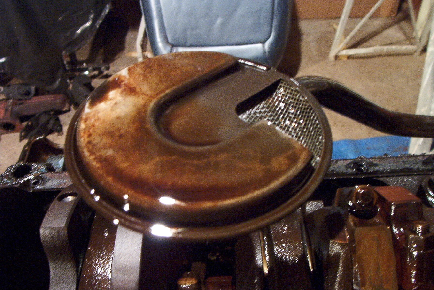 |
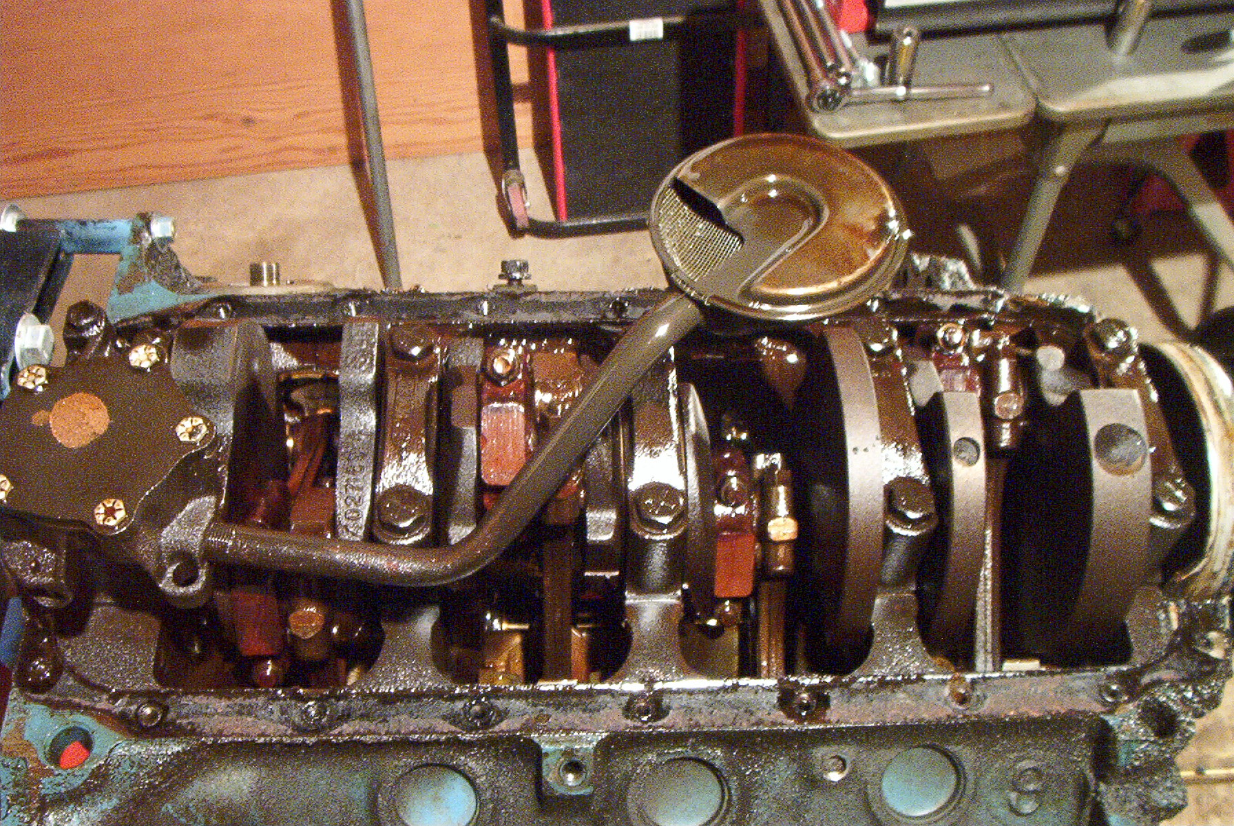
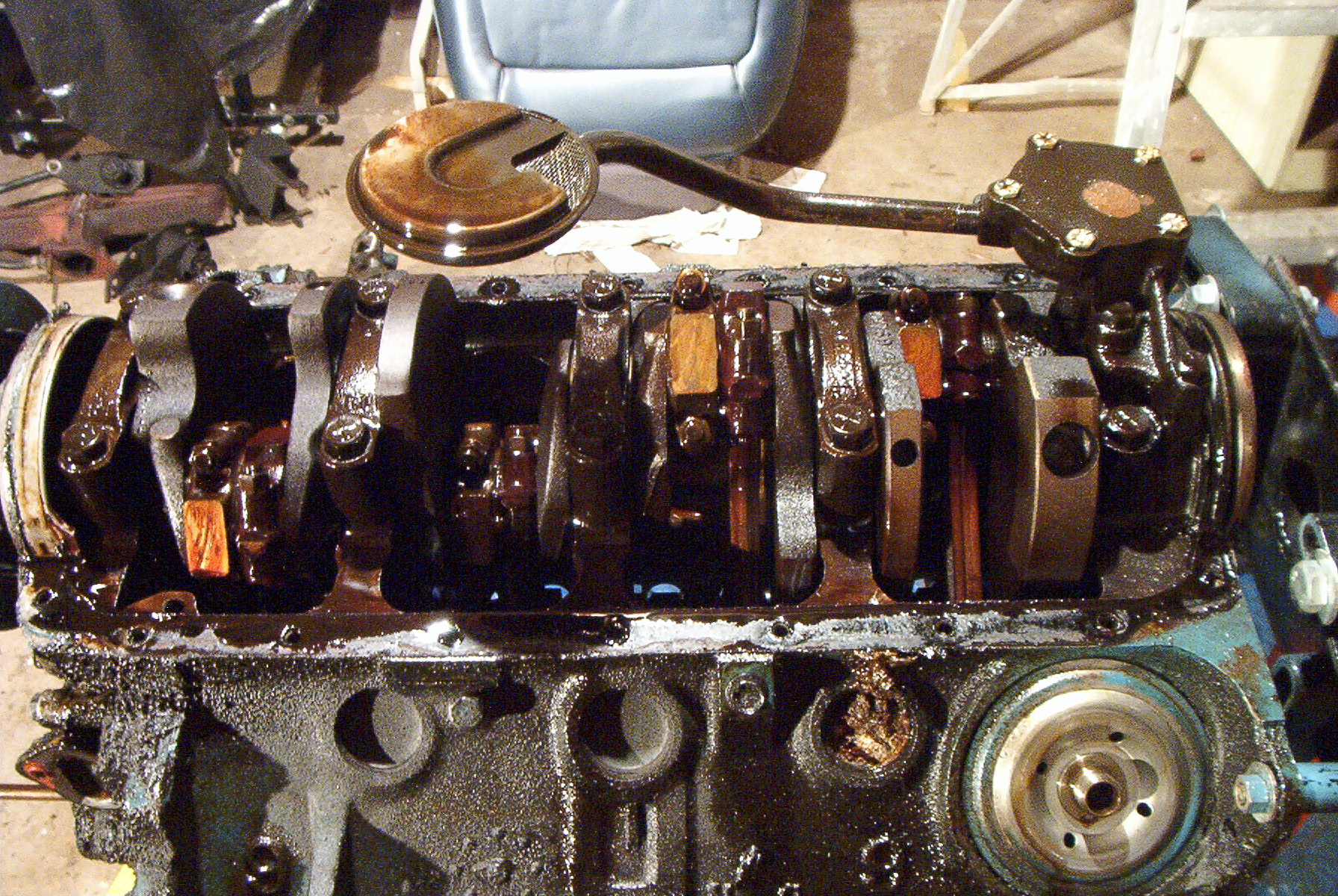
The oil pickup. This contacts the bottom of the oil pan and slightly bent up when the pan is securely fastened to the block. |
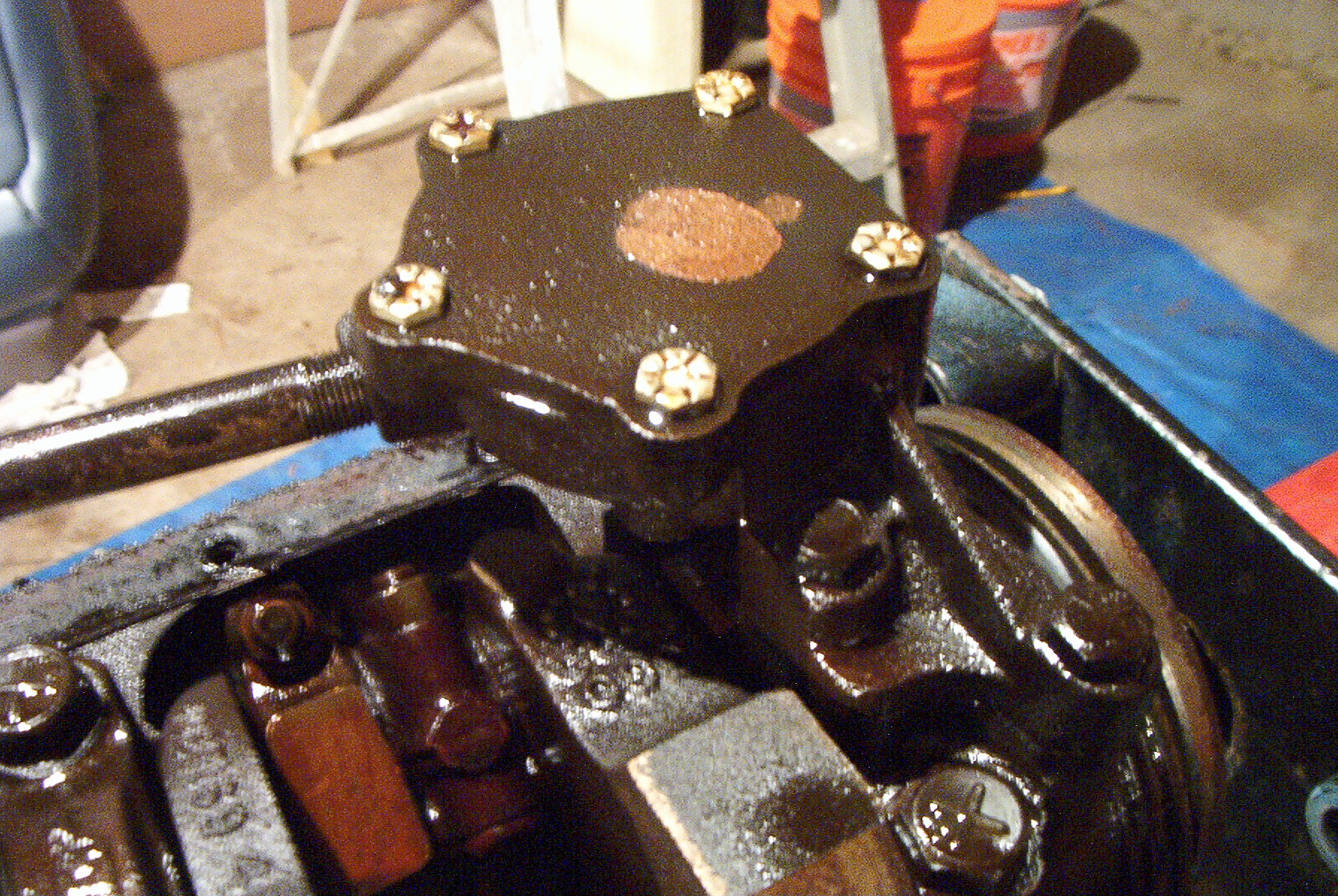 |
The oil pump. |
 |
The oil pump is removed. The
smell of stale, gas-infused oil was worse than 80w-90 gear oil, but
somehow marvelous. The timing cover was also removed at this point, but no photos were taken of this operation. |
 |
Oil pump mounting bosses on the rear main cap. |
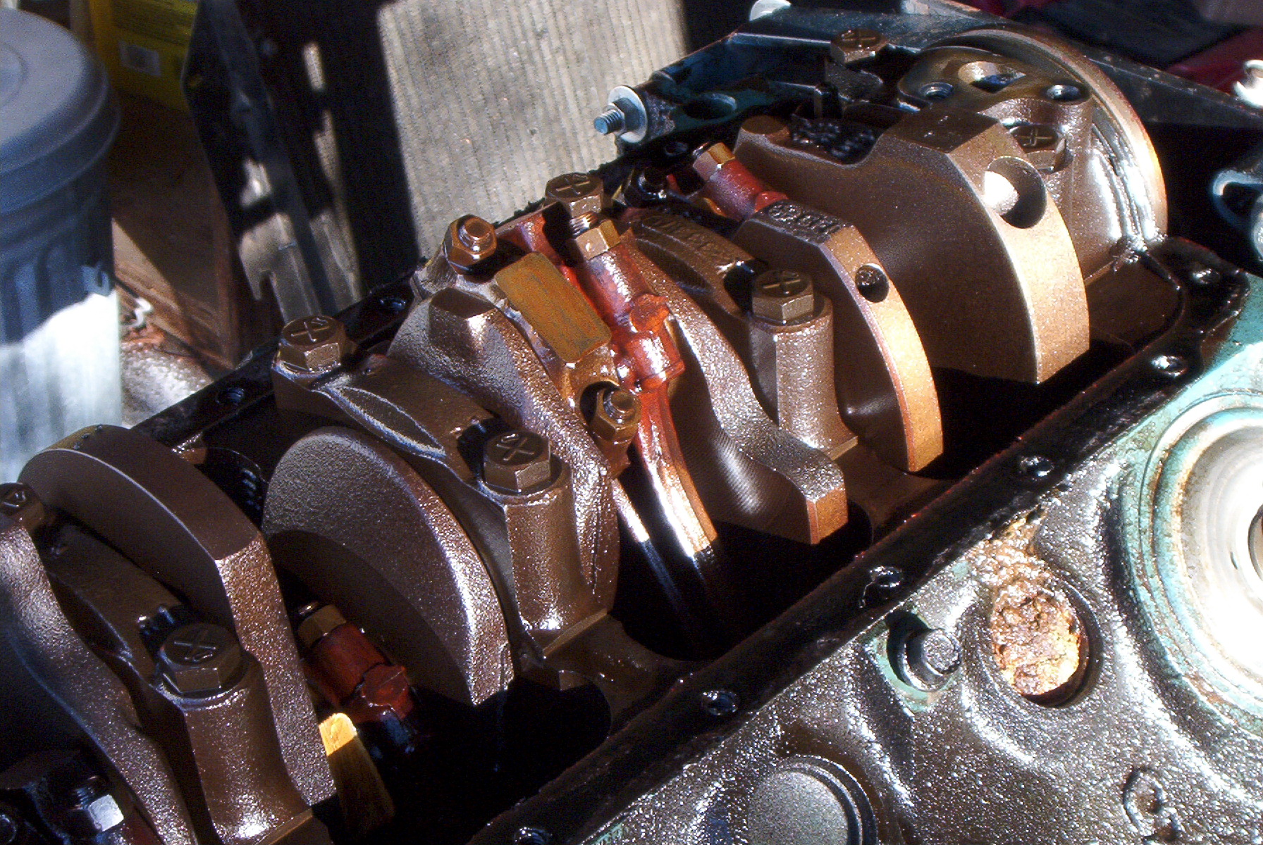 |
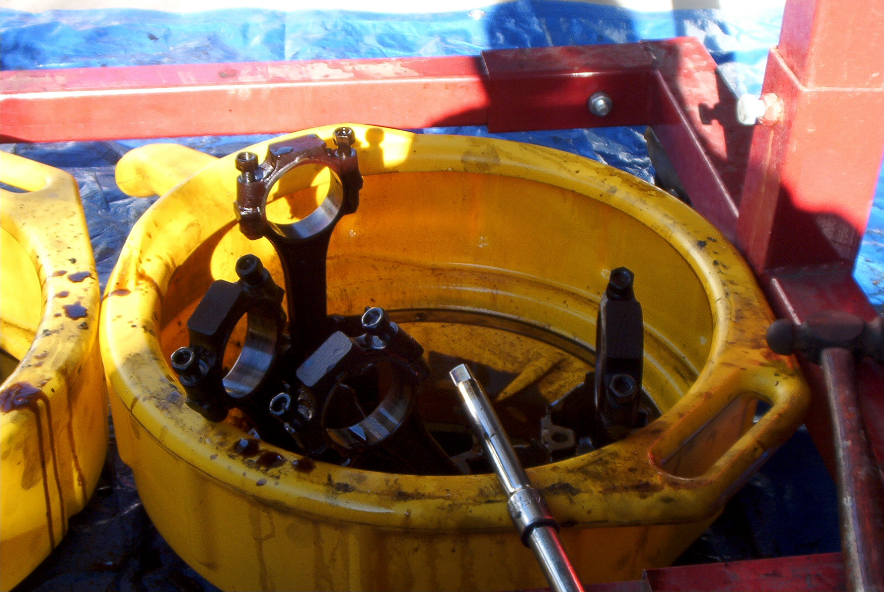
The rods were an odd red color. I'm not sure if it's a stain from the oil, or if the rods were that color when installed. |
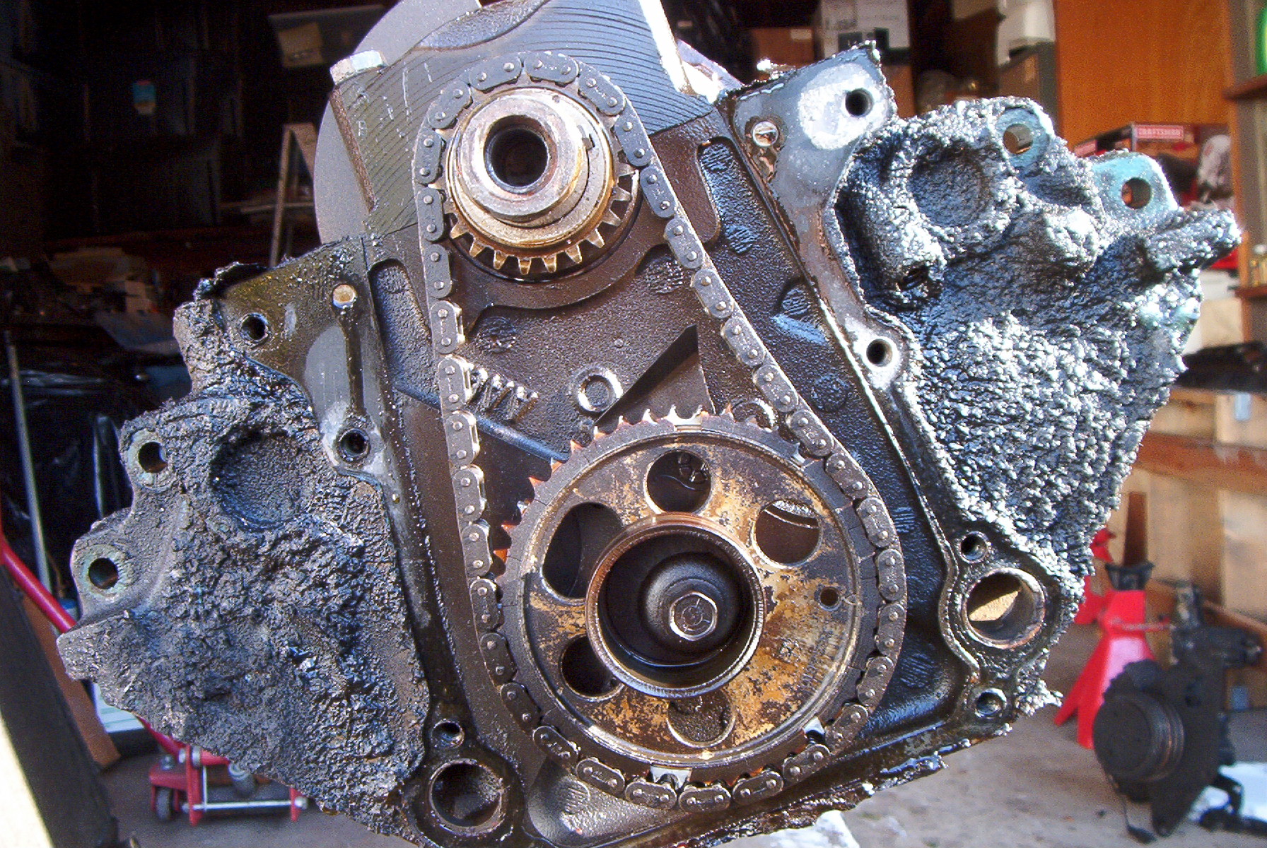 |
Timing gears and chain, and the fuel pump eccentric. |
 |
Close up of the camshaft drive gear. |
 |
Base shot of timing chain tension. |
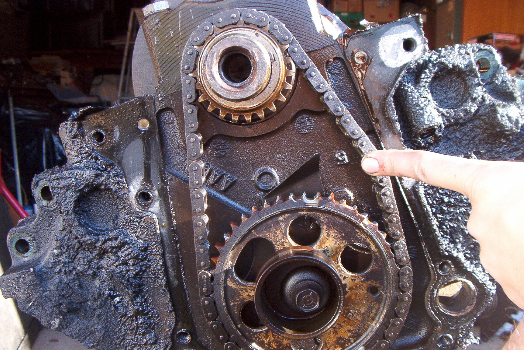 |
Total timing chain deflection. By my estimate, it was at least an inch of deflection. Acceptable deflection is a quarter inch, if that. |
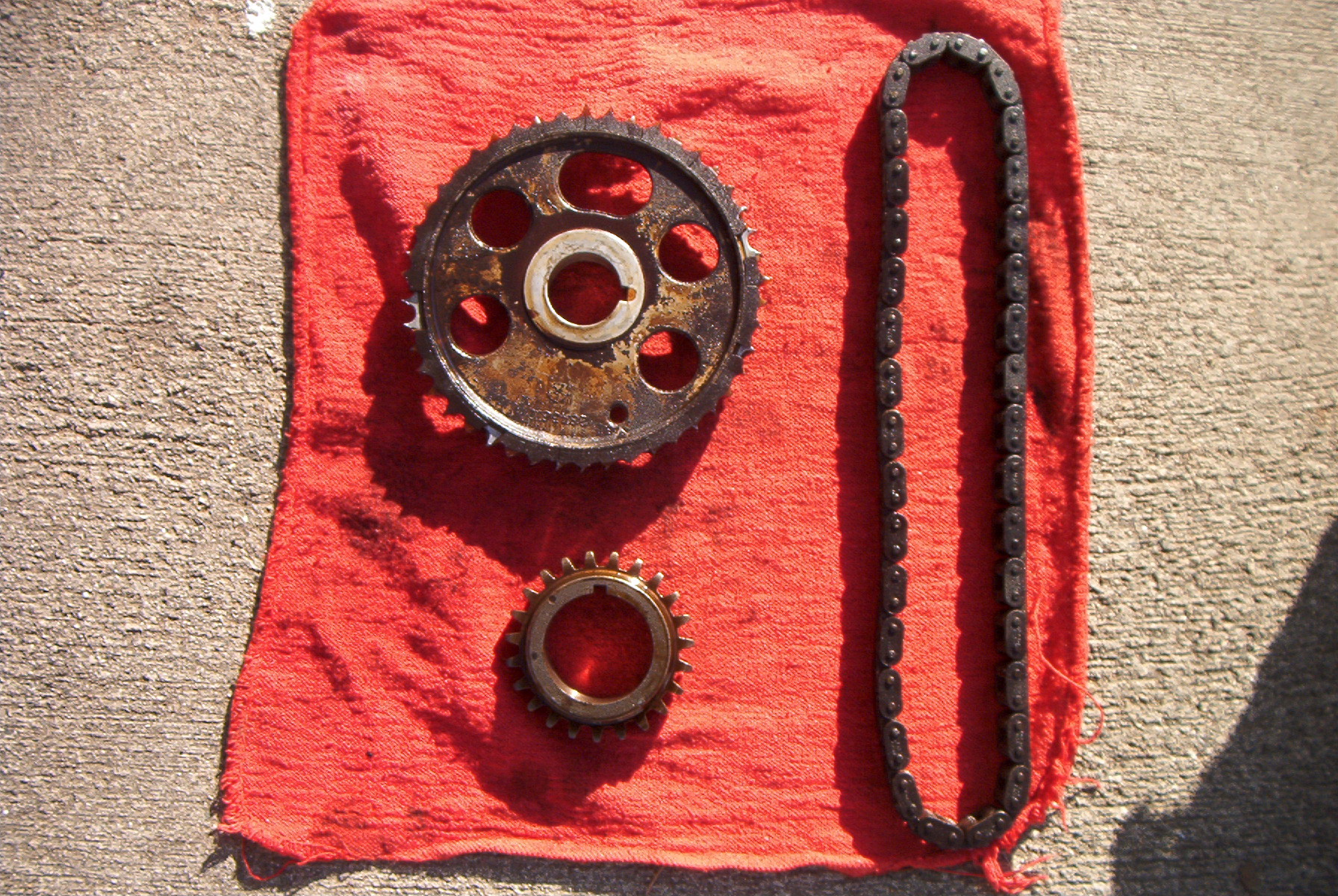 |
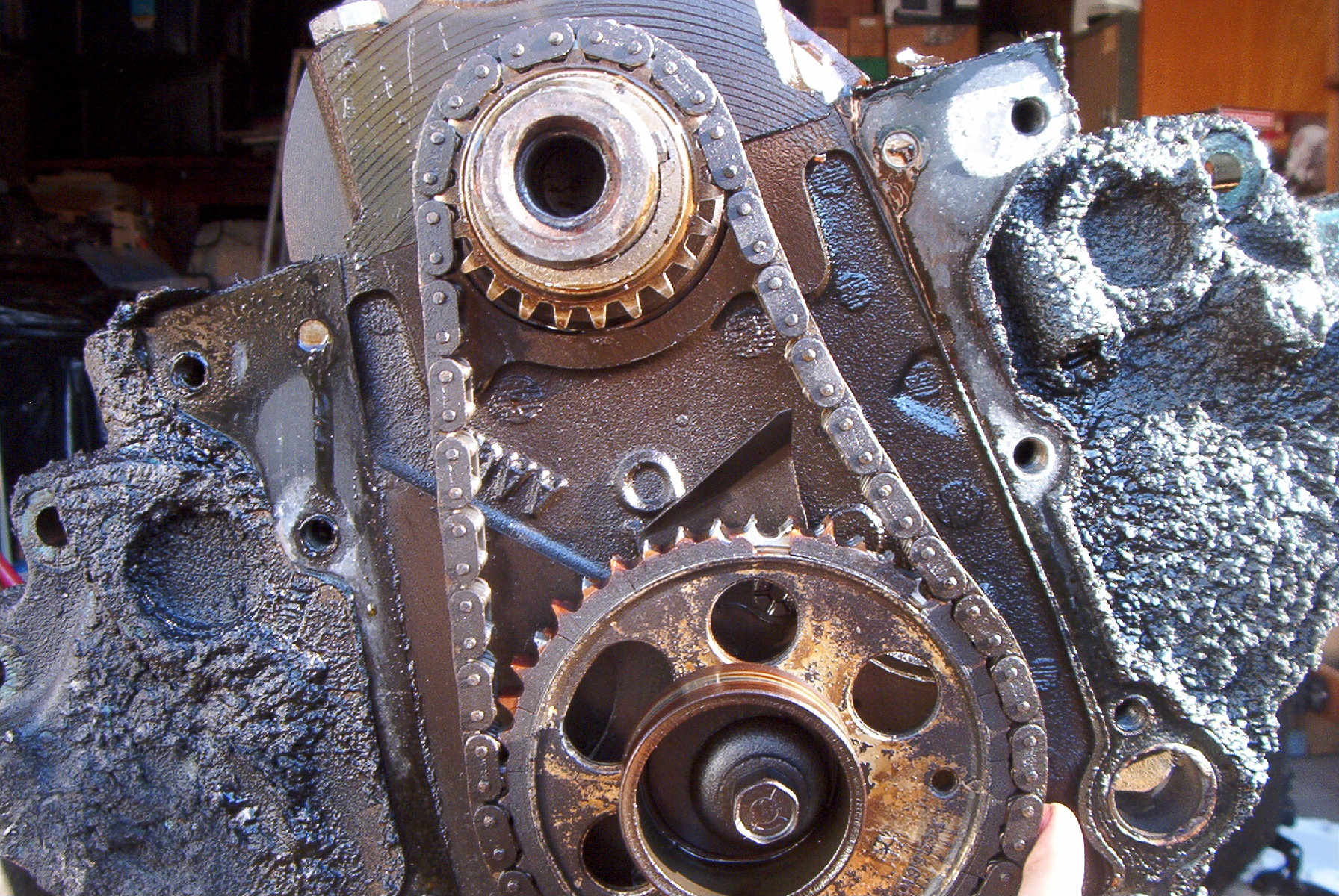
Timing gears and chain set. |
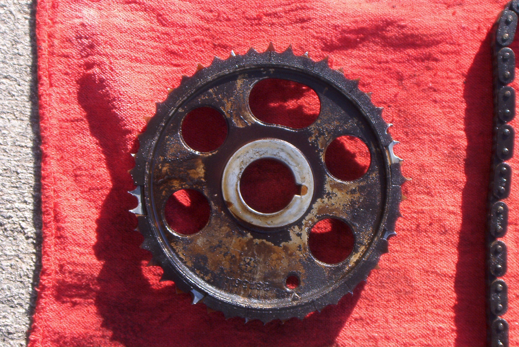 |
Close up of the camshaft drive gear. Note the missing chunks of nylon and the general state of the teeth. |
 |
Camshaft retainer plate, and proper placement of oil diverter and bolts. |
 |
All four pistons on the right side are removed. |
 |
The first four pistons. I didn't have a stamping kit, so I merely wiped off the rod cap and wrote the cylinder number on the bearing journal with a sharpie. |
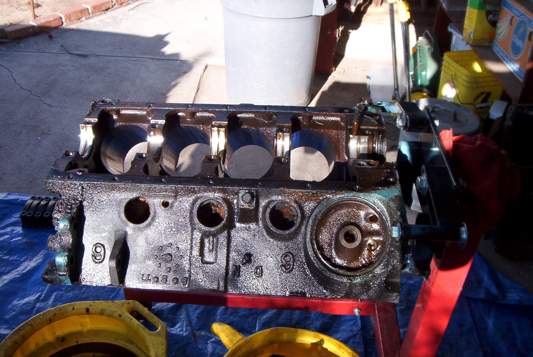 |
The pistons and crankshaft are removed. |
|
|
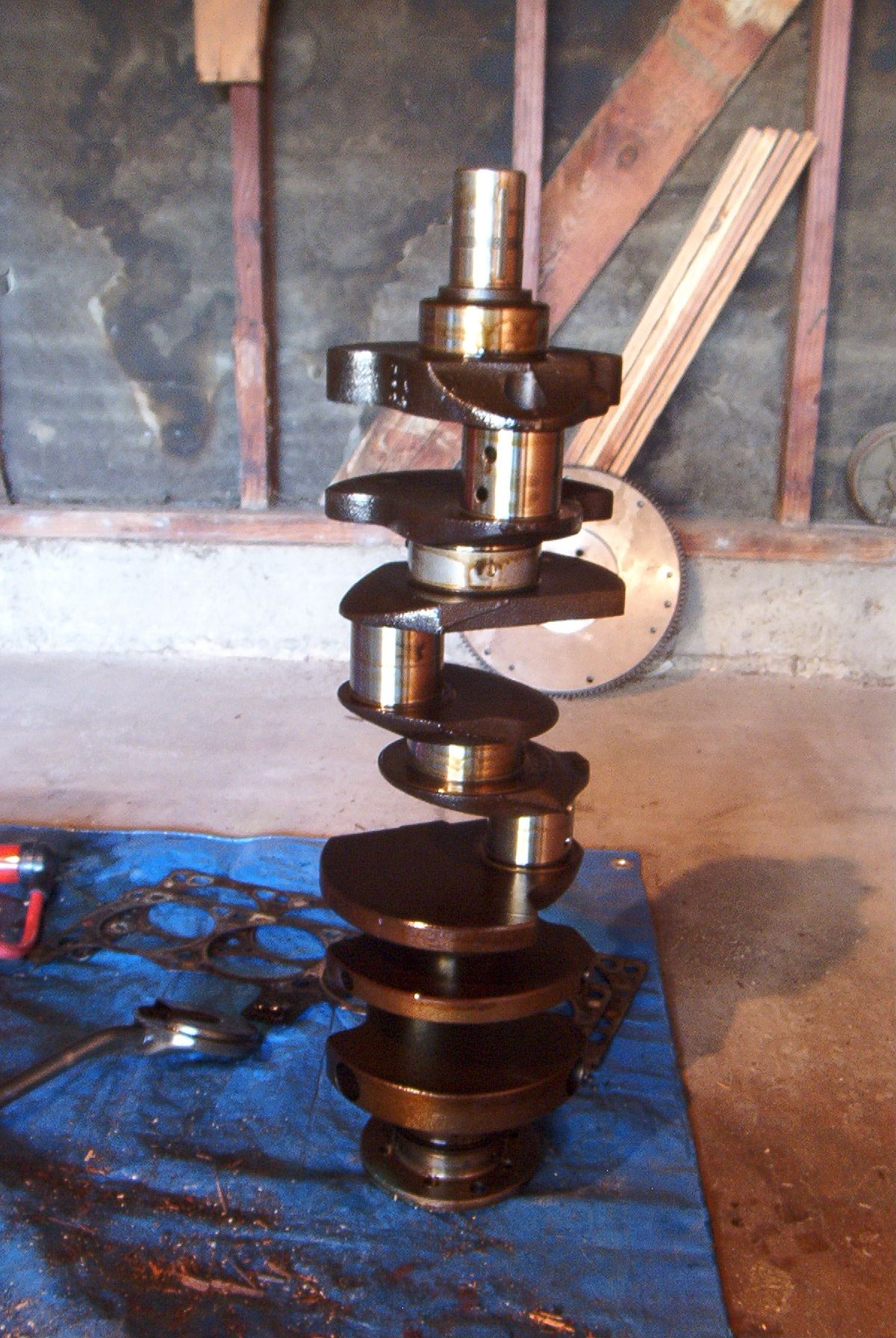
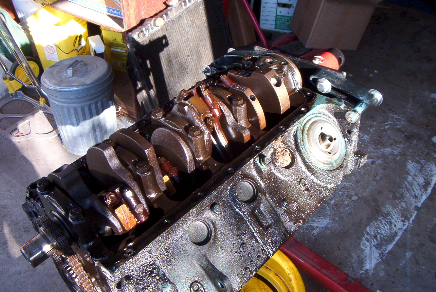
The crankshaft. All the journals were in excellent shape, with no scratches, pitting, or any real wear. A slight polish and it would be good as new. |
 |
How to remove a camshaft without the tool or a bolt to thread into the cam snout. This method is only advisable if you're not going to reuse the camshaft. |
 |
The cam sometimes gets stuck, and a little more persuasion is needed until enough is sticking out of the block so that it can be simply pulled out. |
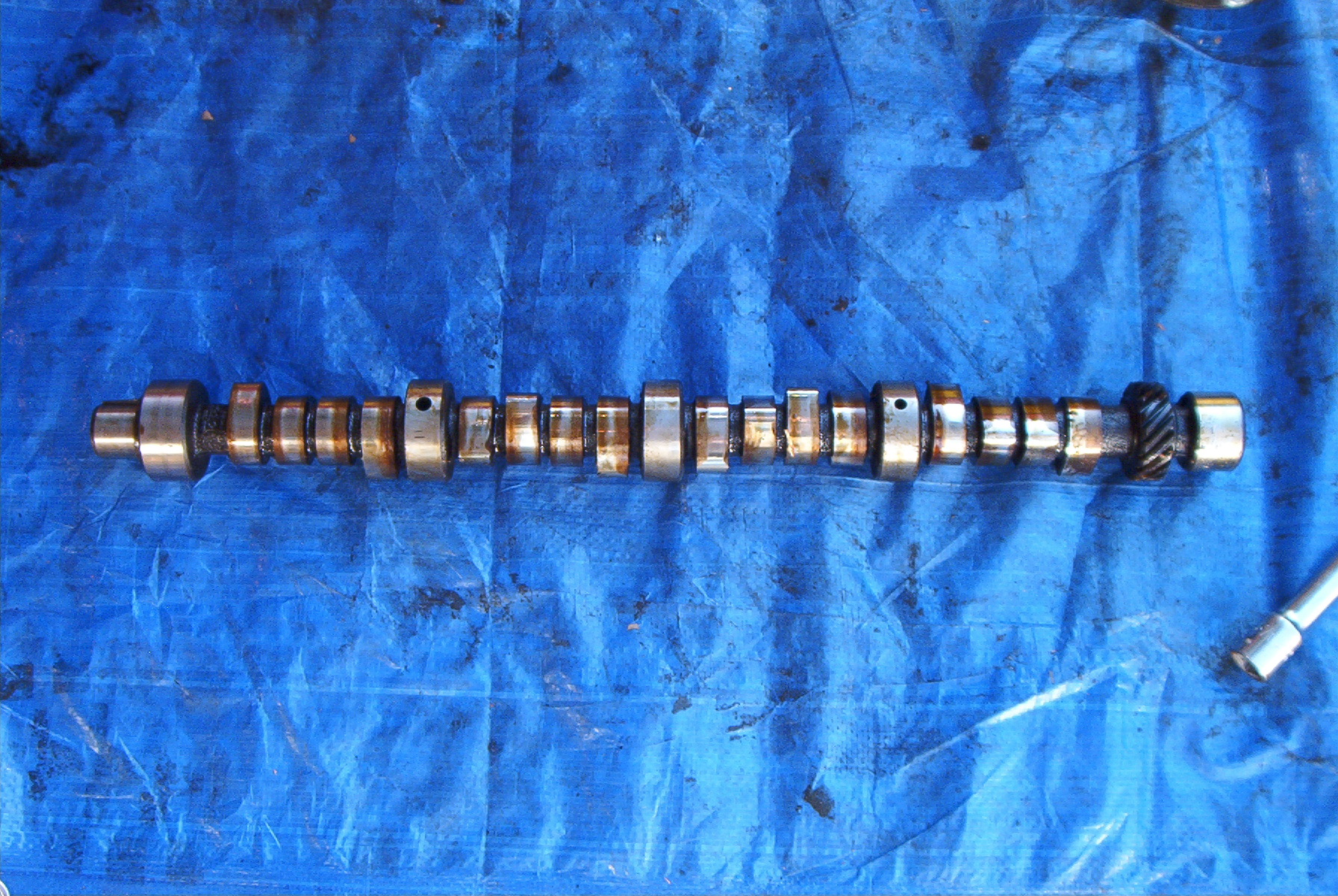 |
The camshaft. This can be considered the brain of the engine, telling the valves when to open and close. Change the degree and lobe separation angle, and you change the personality of the engine. |
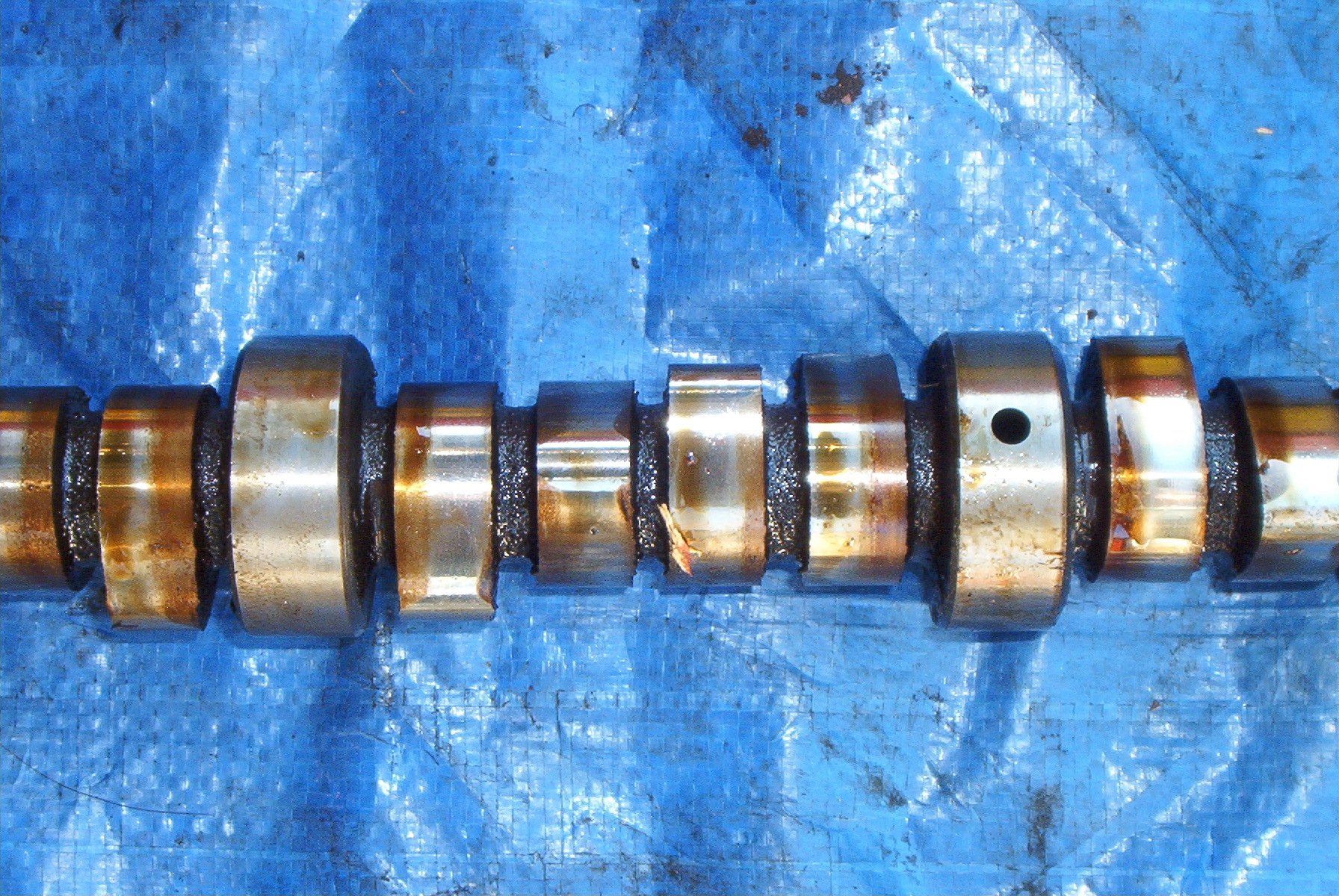 |
A close up of the camshaft lobes and journals. As shown by the dark patches, this camshaft has seen some serious use and would not be a good item to reuse. |
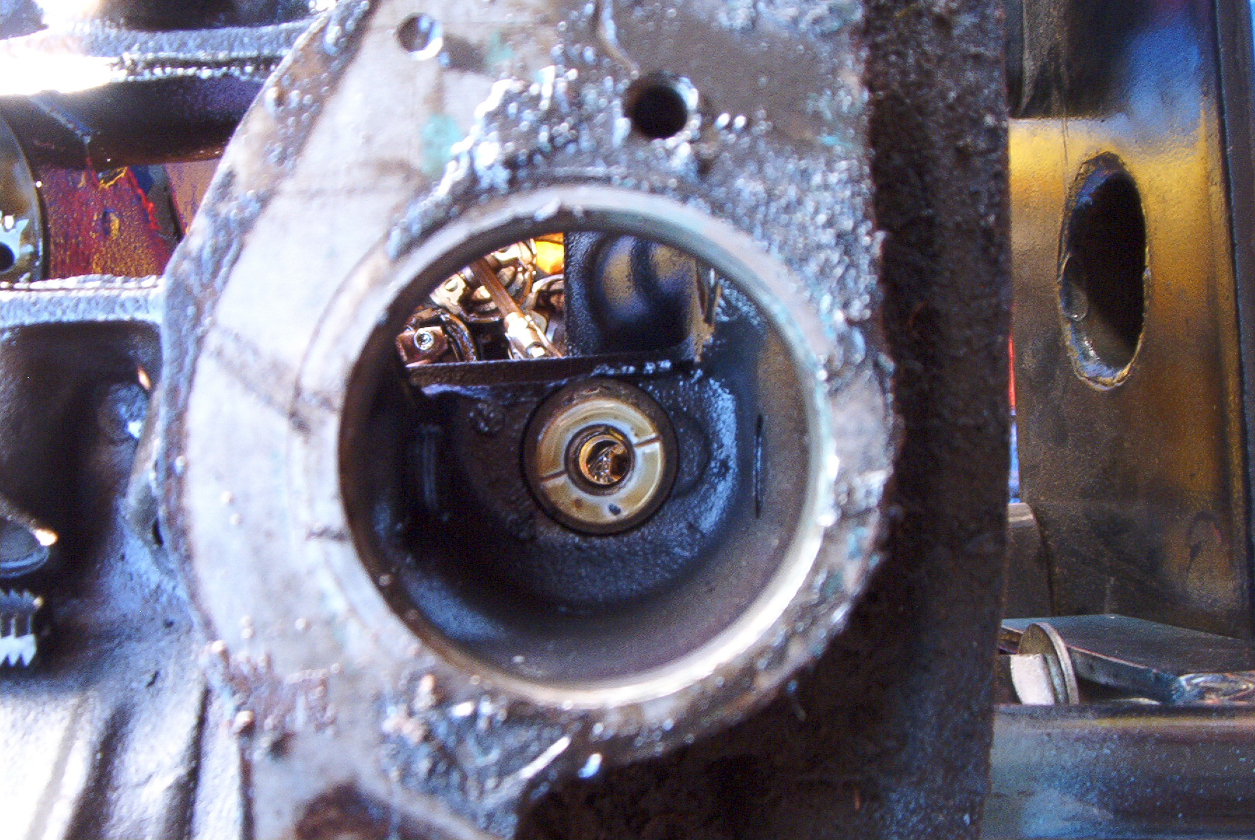 |
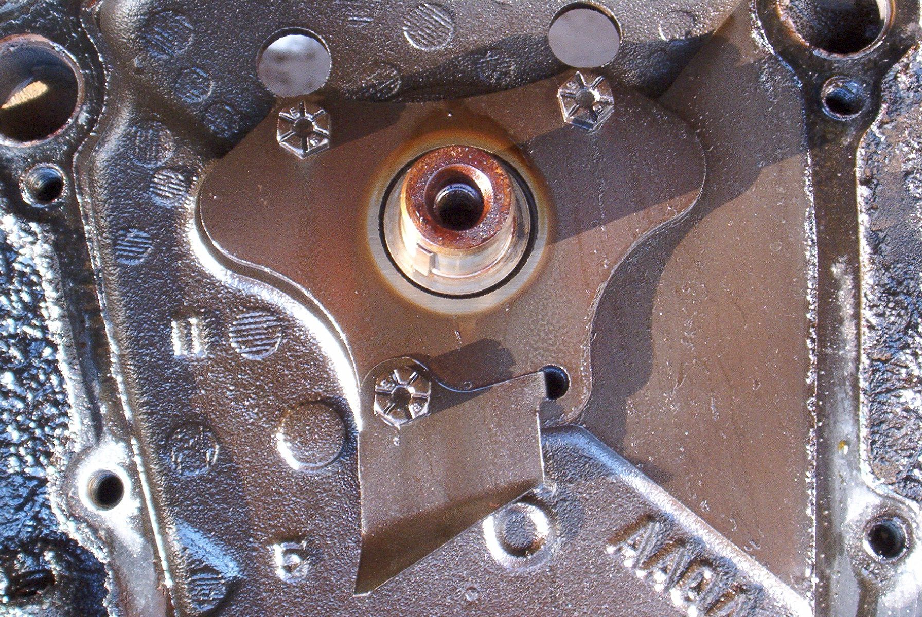
The tan object in the middle of the photo is the distributor bushing. This bushing holds the distributor gear and oil pump driveshaft in place, so that it doesn't wander around and destroy itself. It is pressed into the block and reamed with a special tool. Most stock bushings are made from nylon, but aftermarket bushings are made from bronze. |
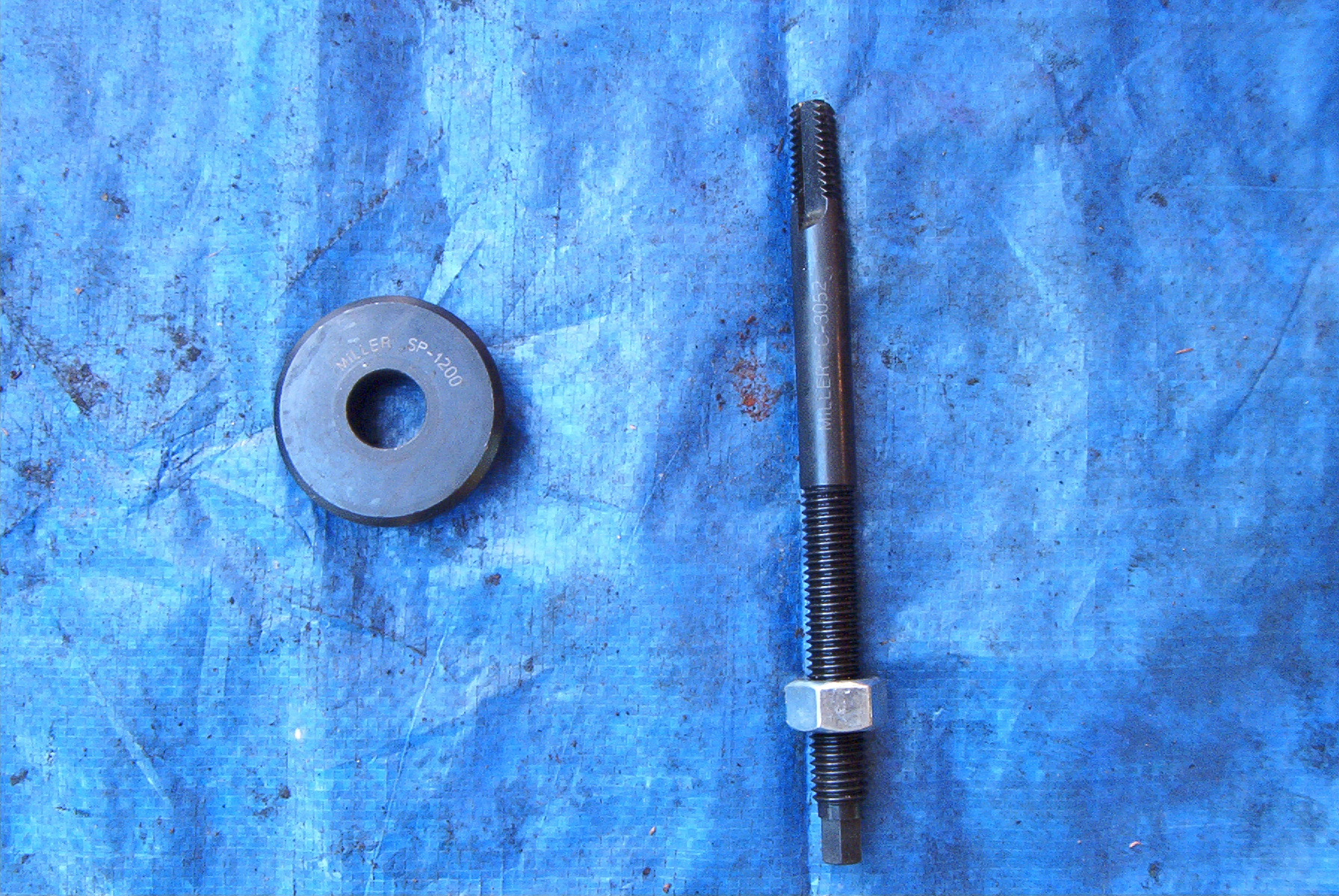 |
This is the distributor bushing removal tool.
This is not a required tool, as the bushing can be driven out with a
long punch from the bottom of the block, but it's just the easiest
way of doing things. Made by Miller Special Tools, part number C-3052. Available at eToolCart, or sometimes on eBay for a vastly reduced price. |
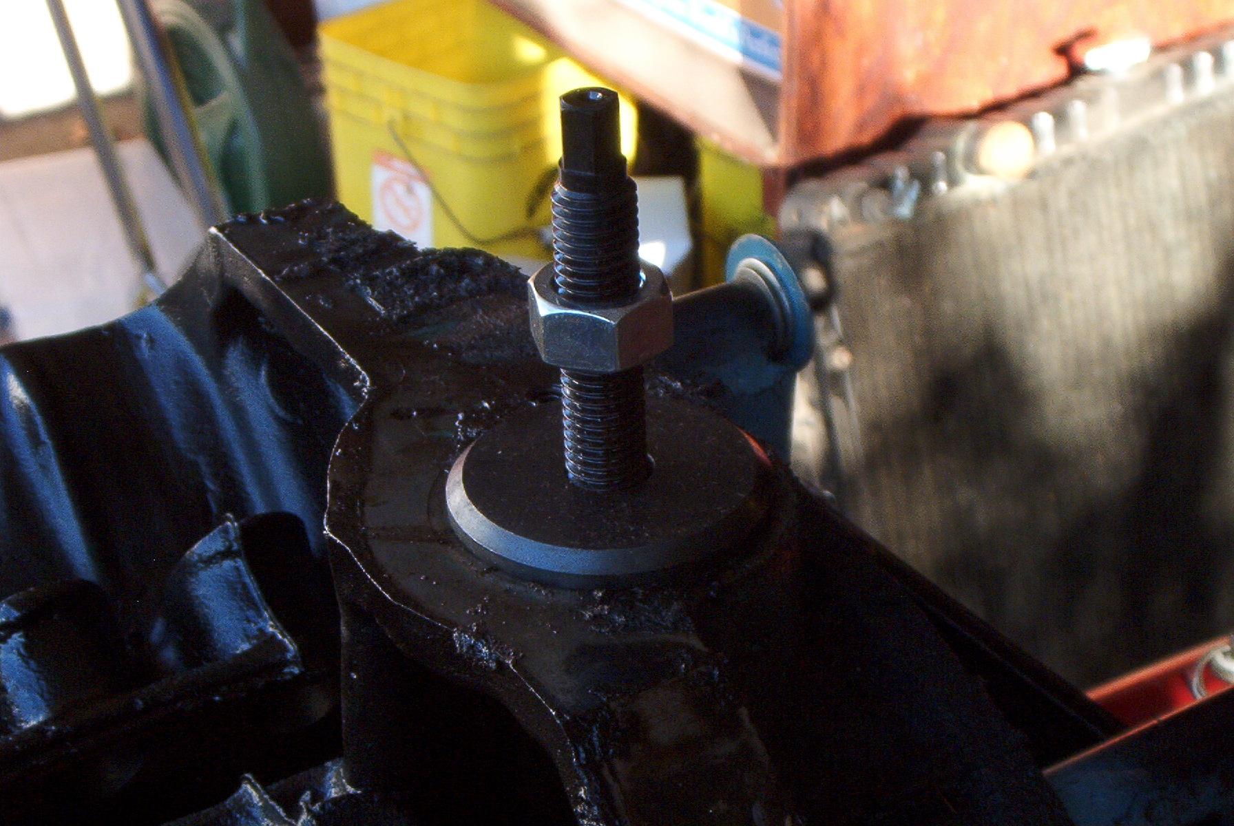 |
The tool is installed in the distributor hole. |
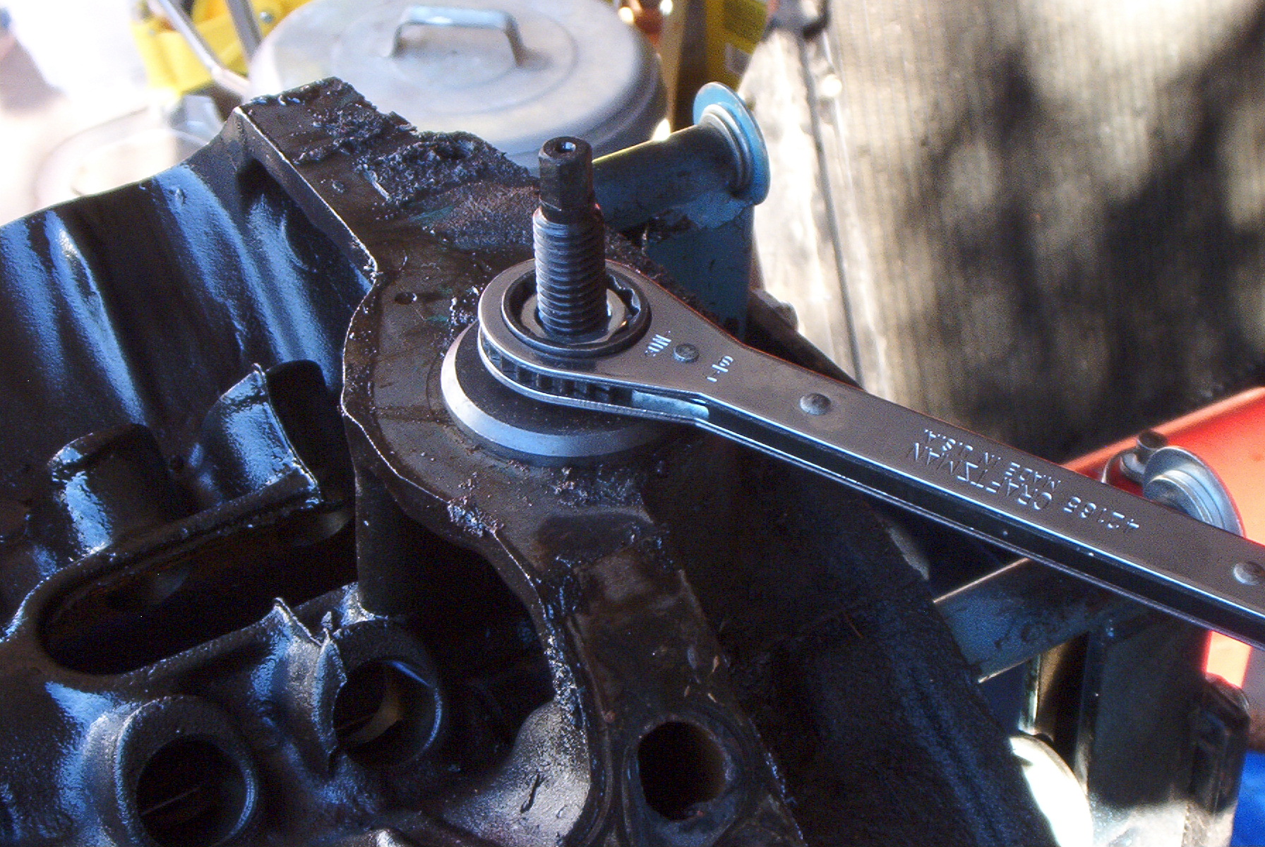 |
To remove the bushing, the nut is threaded all the way down to the base of the tool, then tightened with a wrench. As it moves along the threaded rod, the portion screwed into the bushing is pulled up and removes the bushing from its press fit in the block. |
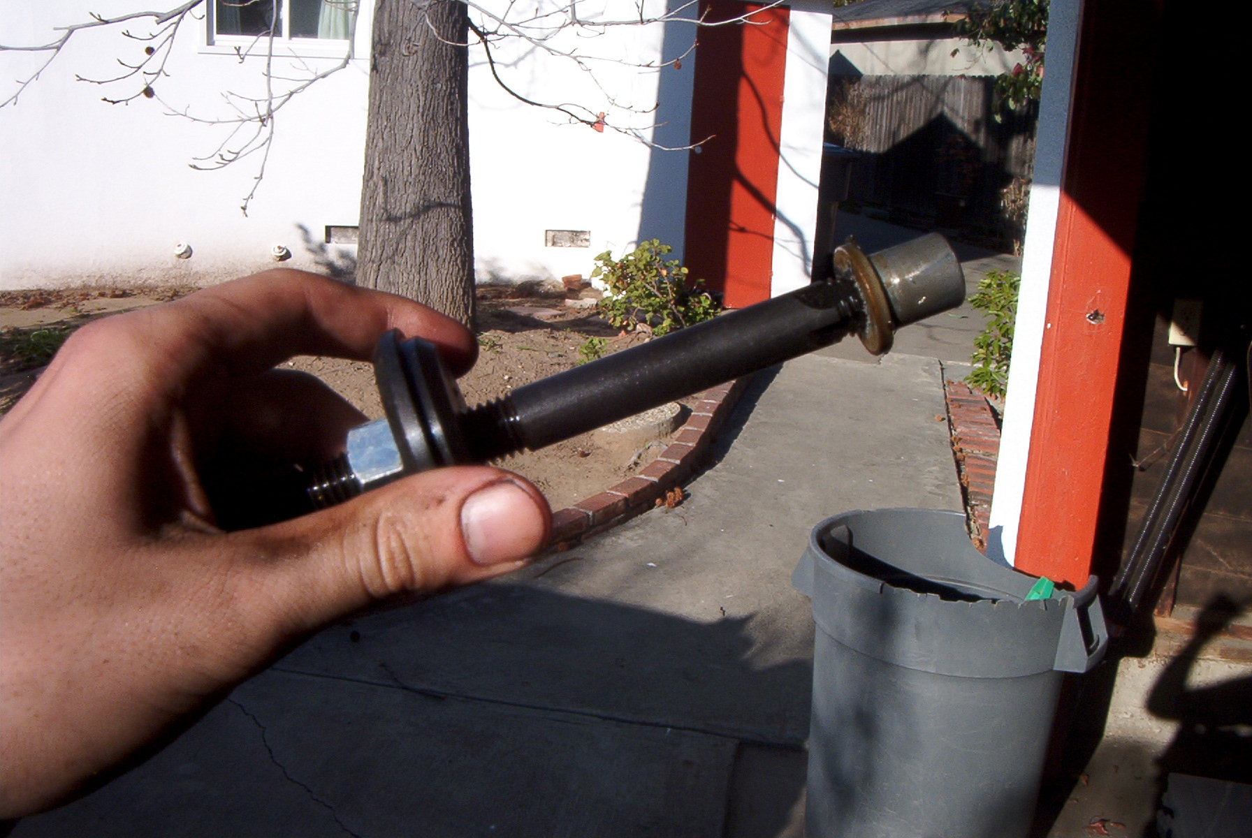 |
The bushing is removed. A quick squeeze from some Vice Grips broke it apart and got it off the tool. |
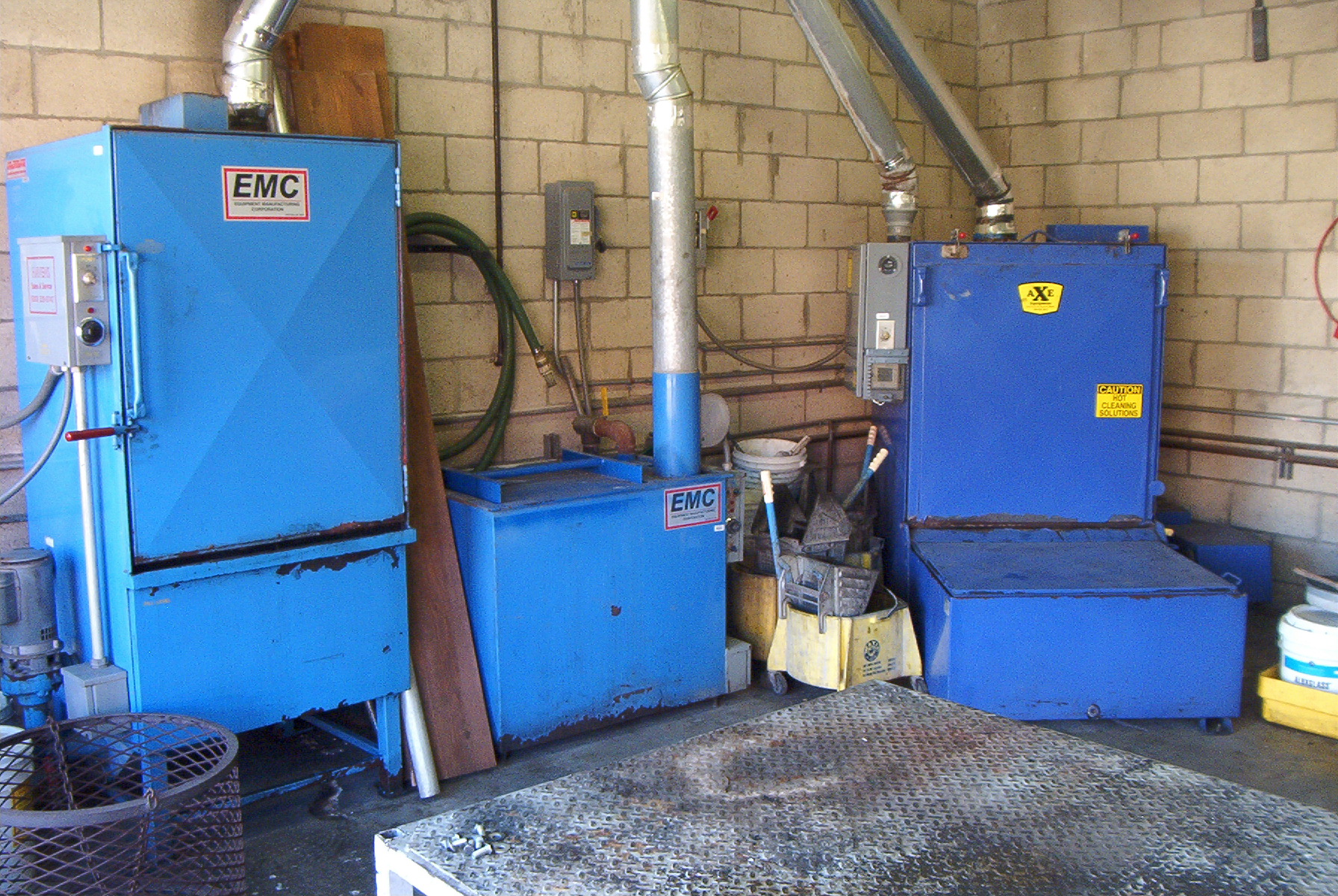 |
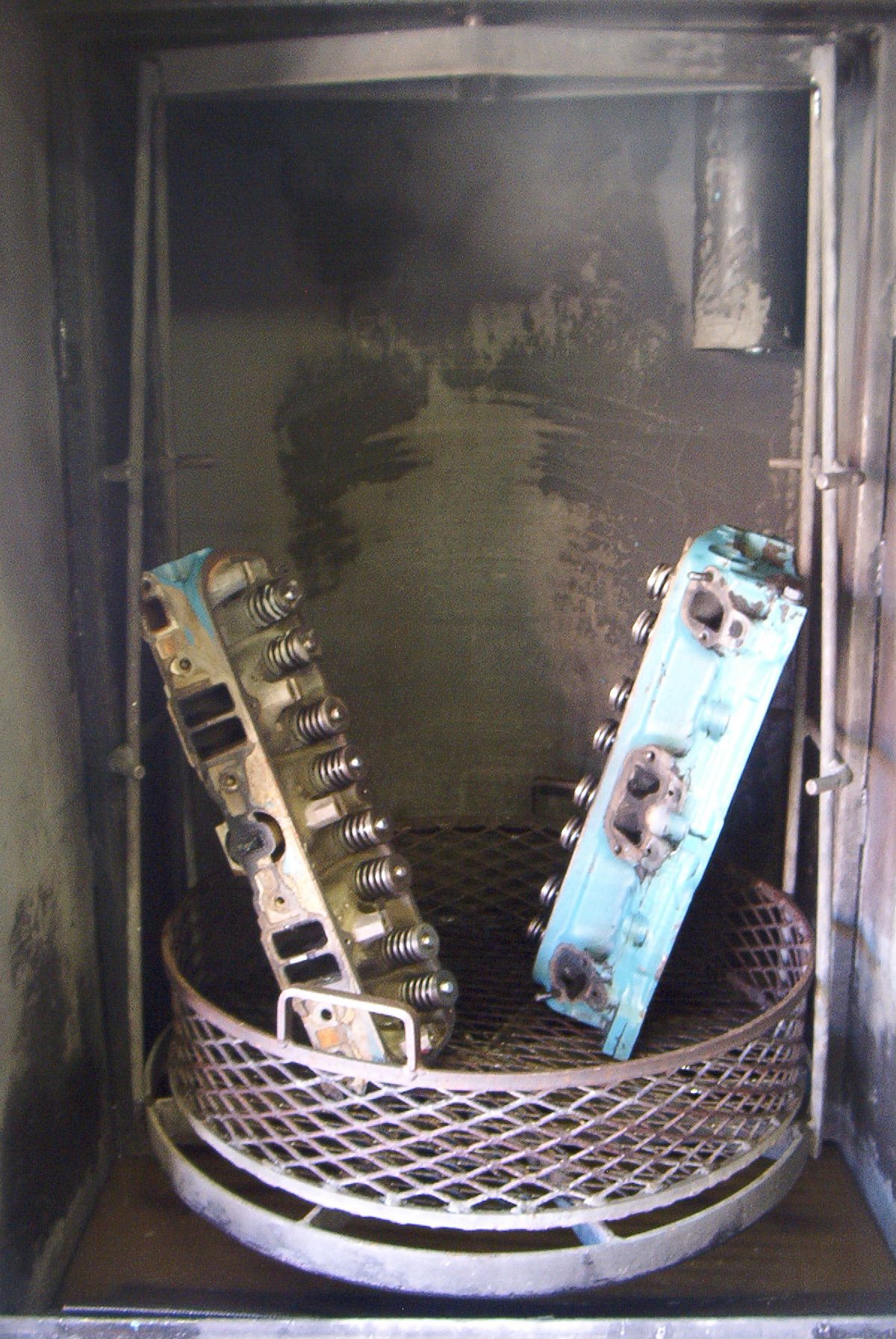
The hot tanks. These use a water based solvent heated to between 140 and 160 degrees, which is then sprayed from multiple directions onto a rotating cage, in which the parts are placed. Depending on the amount of sludge, they either work really well, or not at all. |
 |
Some parts, after hot tanking. |
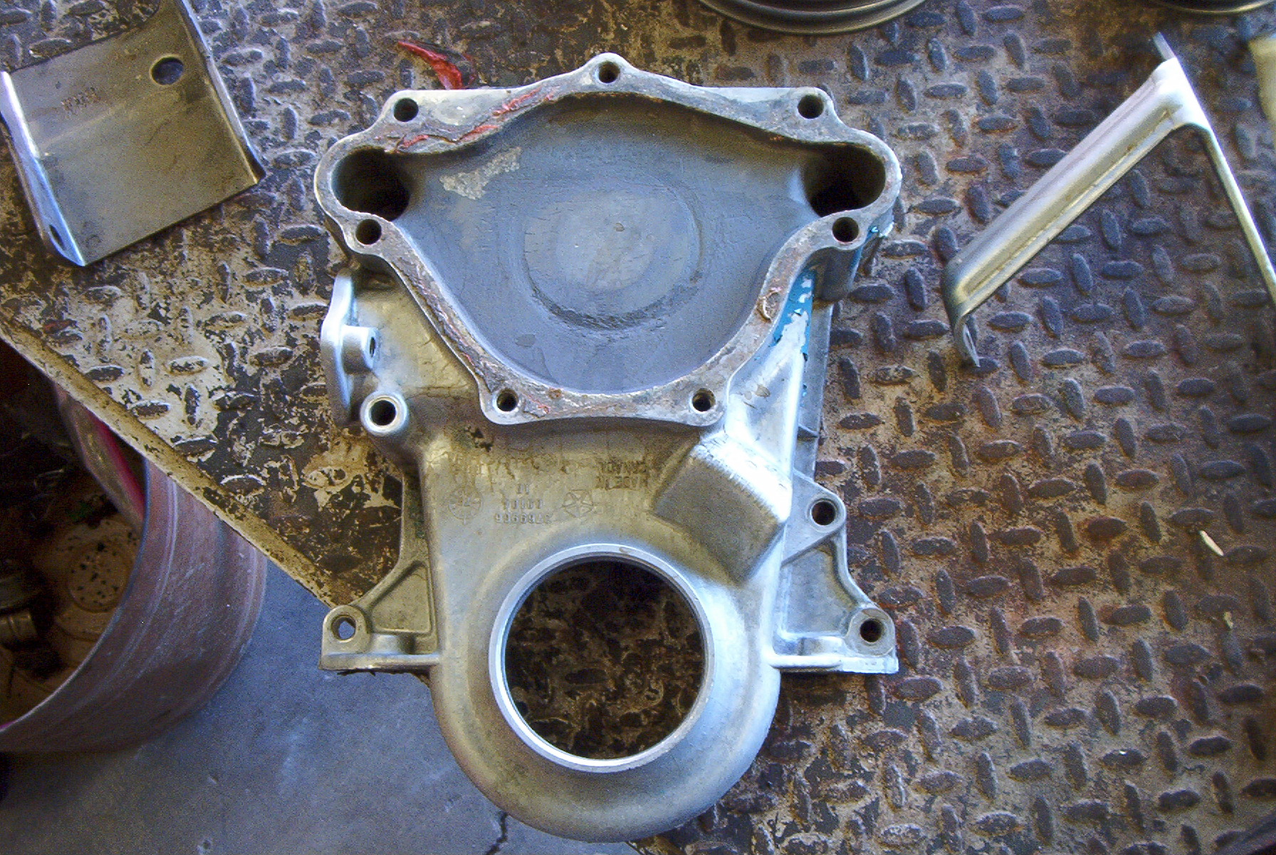 |
Clean timing cover. |
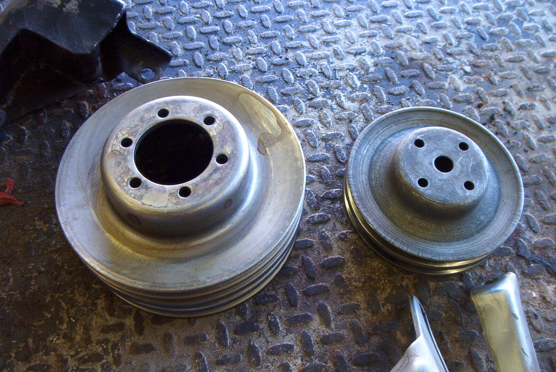 |
Clean pulleys. |
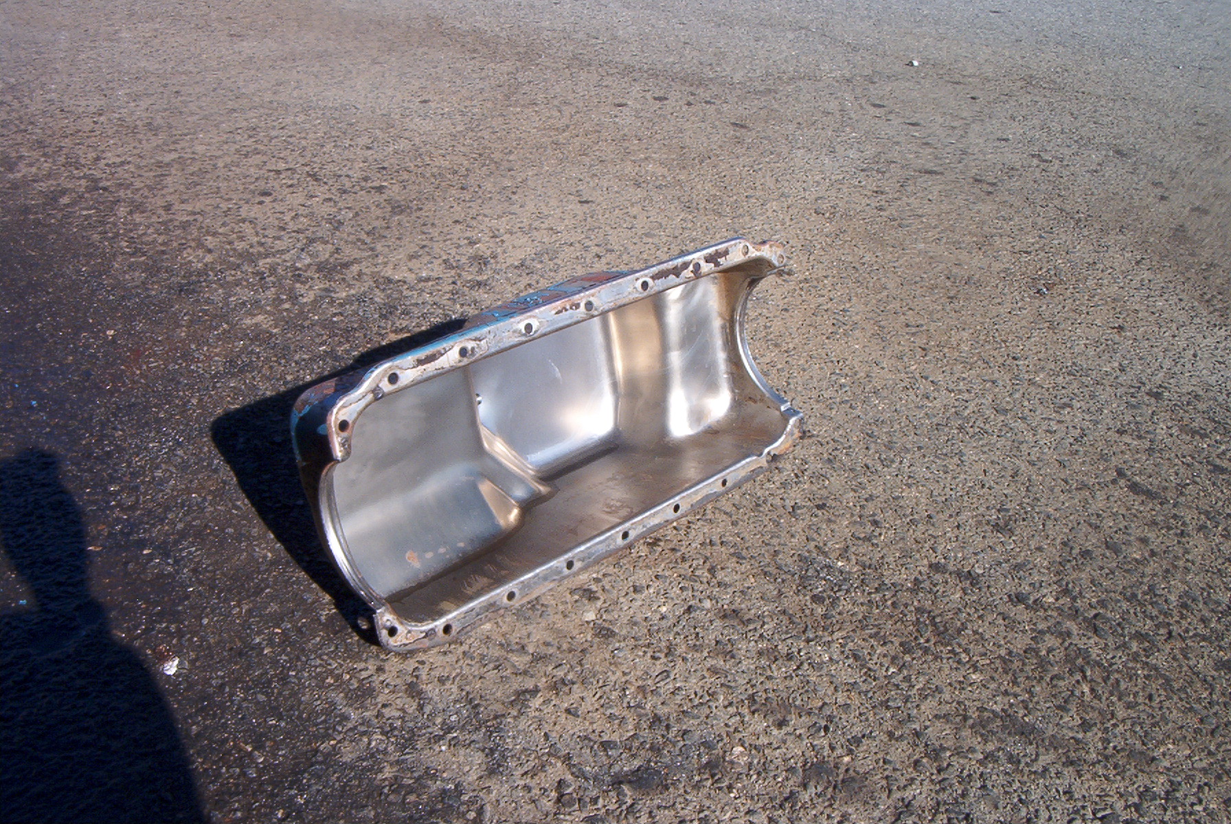 |
Shiny clean pan. |
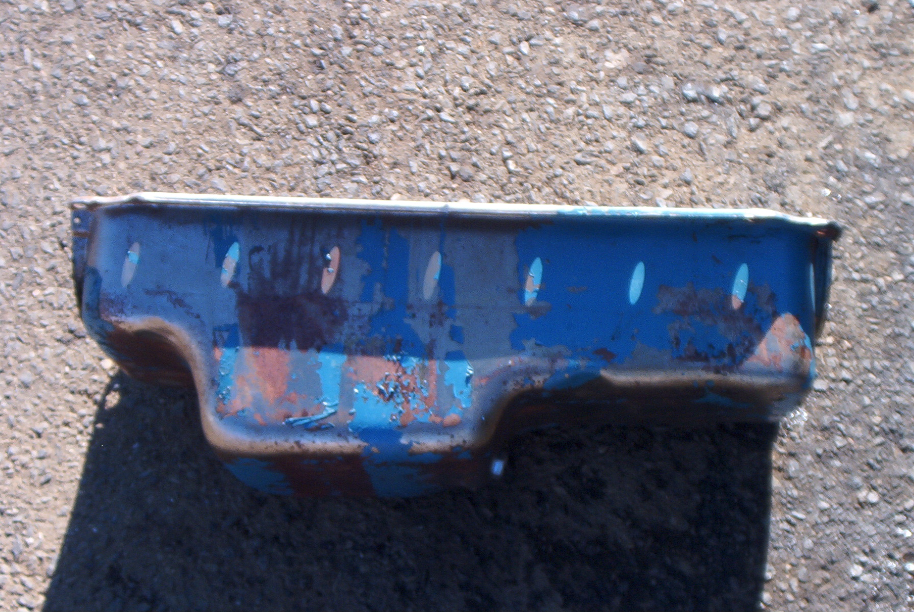 |
Remember all that crap on the side of the pan? Gone. Along with some of the paint. |
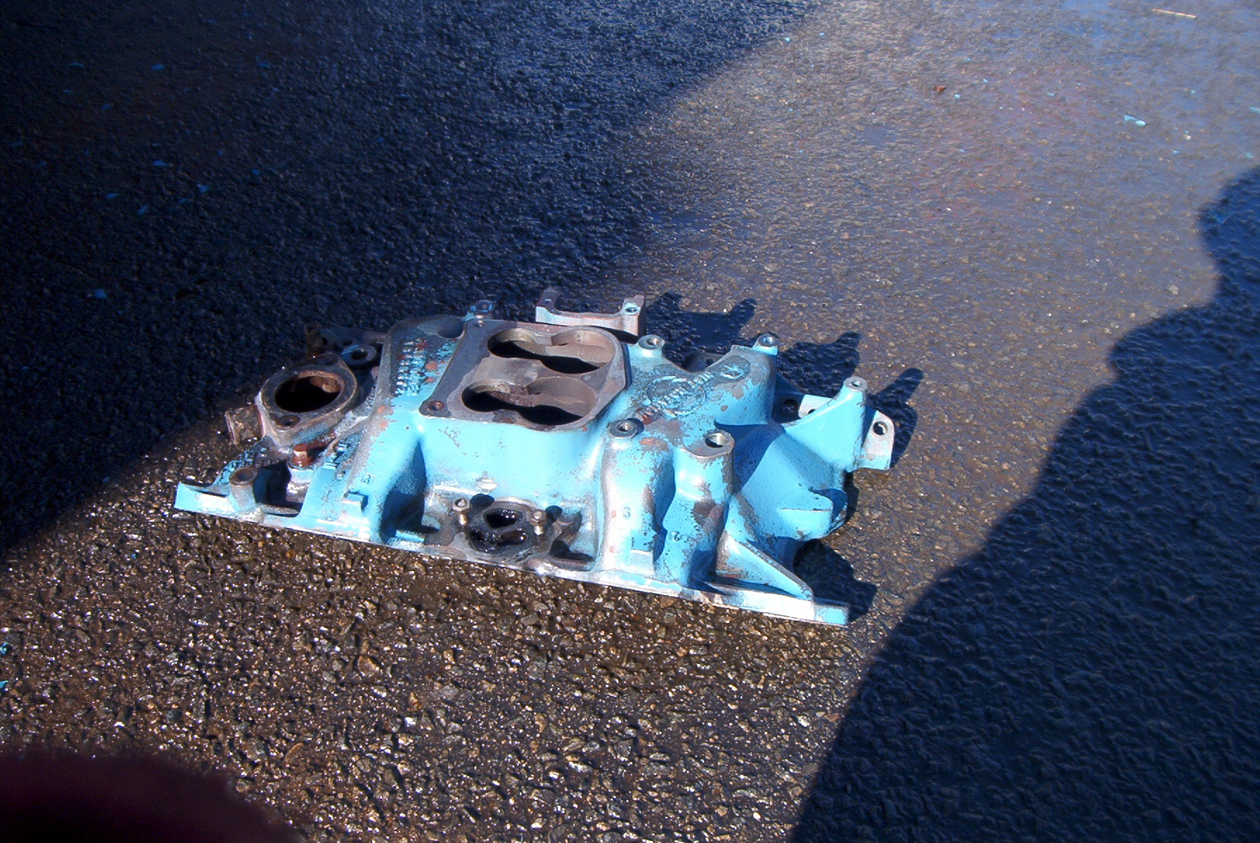 |
A nice clean manifold. |
|
|
The heads, after being hot tanked. |
|
|
Close up of one head. Still a bit dirty, but clean enough to work on. |
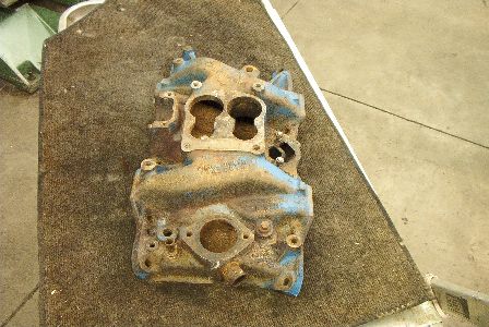 |
The intake manifold, after hot tanking but before bead blasting. All the carbon in the EGR passages has been chiseled out and filed down as well. |
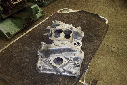 |
The intake manifold, after bead blasting. |